



Table of contents: General 🠇 Speedometer 🠇 Tachometer 🠇 Analogue clock 🠇 Digital clock 🠇 Fuel gauge, temperature gauge and…🠇 Printed circuit 🠇
General
1. Remove the instrument panel as described in Section 9, then proceed as described under the relevant sub-heading.
Speedometer
2. Working at the rear of the instrument panel, remove the three screws securing the lens assembly (see illustration).
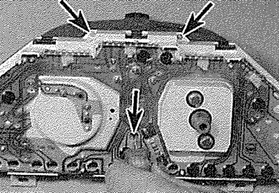
10.2. Remove the securing screws (arrowed)...
3. Using a flat-bladed screwdriver, carefully release the lens assembly securing clips, then withdraw the lens assembly (see illustrations).
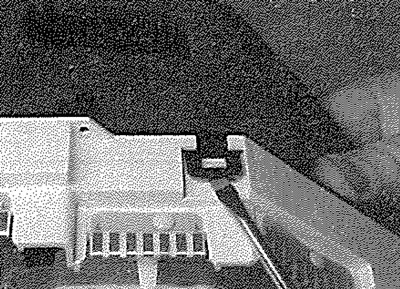
10.3a.... then release the securing clips...

10.3b.... and withdraw the lens assembly
4. Working at the front of the speedometer, unscrew the two securing screws (see illustration).
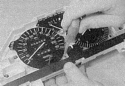
10.4. Removing a speedometer front securing screw
5. Remove the two securing screws from the rear of the speedometer and recover the bushes, then withdraw the speedometer from the instrument panel (see illustrations).
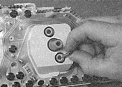
10.5a. Remove the speedometer rear securing screws...
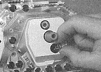
10.5b.... and recover the bushes...
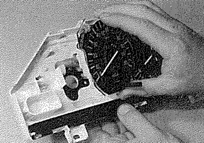
10.5c.... then withdraw the speedometer
Original text is located at www.PeugeotBook.ru
6. Refitting is a reversal of removal.
Tachometer
7. Proceed as described in paragraphs 1 to 3.
8. Working at the front of the tachometer, unscrew the three securing screws.
9. Working at the rear of the tachometer, remove the securing nuts.
10. Where applicable, pull the adjustment knob from the digital clock button, then withdraw the tachometer.
11. Refitting is a reversal of removal.
Analogue clock
12. Proceed as described in paragraphs 1 to 3
13. Working at the front of the clock, unscrew the three securing screws (see illustration).
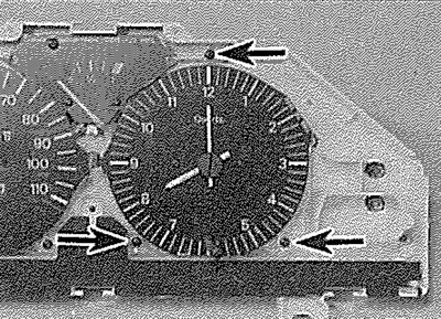
10.13. Clock front securing screws (arrowed)
14. Working at the rear of the clock, remove the securing nuts (see illustration), then withdraw the clock.
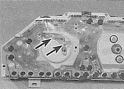
10.14. Clock rear securing nuts (arrowed)
Digital clock
15. Remove the tachometer as described previously in this Section.
16. Carefully unclip the clock from the instrument panel.
17. Refitting is a reversal of removal.
Fuel gauge, temperature gauge and oil pressure gauge
18. Proceed as described in paragraphs 1 to 3.
19. Working at the front of the gauge, remove the securing screw.
20. Working at the rear of the gauge, remove the securing nut, then withdraw the gauge from the instrument panel.
Printed circuit
21. Remove all the instruments as described previously in this Section.
22. Remove all the bulbholders from the rear of the instrument panel, by twisting them in an anti-clockwise direction. Slacken and remove all the circuit securing screws, then release the printed circuit from the retaining pins and remove it from the rear of the instrument panel.
23. Refitting is a reversal of removal, ensuring that the circuit tracks are not damaged and that the circuit is correctly located on all the retaining pins.