



Table of contents: Heater control unit (models before…🠇 Heater control unit (models since…🠇 Heater fan 🠇 Heater 🠇
Heating and ventilation system
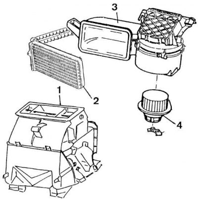
1 – air distribution box, 2 – heater radiator, 3 – air supply housing, 4 – fan
Heater radiator
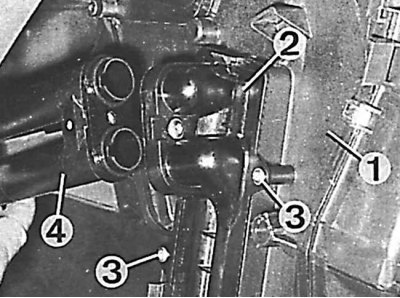
1 – ventilation system housing, 2 – heater radiator, 3 – mounting screws, 4 – pipes
There are two types of heating systems. On basic models, the heating system is controlled manually. On more expensive models, the heating system is controlled electronically. Both systems are identical, except for the control unit.
The control unit is located in the panel and uses flap flaps to control the distribution and mixing of air supplied to the cabin through the various parts of the system.
Cold air enters through a grille at the rear of the engine compartment. Air from the passenger compartment is removed through ducts at the rear of the car. The incoming air is heated by heated coolant.
The recirculation switch closes the fresh air supply, while the air inside the car is constantly circulated.
Attention! To repair the heating and ventilation system, you must remove the steering wheel, instrument panel with cover, front walls of the intermediate console, trim of the window sill, instrument cluster and steering column cover.
Heater control unit (models before 1992)
Removal
1. Disconnect the negative cable from the battery.
2. Remove the radio.
3. Lower the steering column to its lowest position.
4. Remove the seat belt buckle control switch.
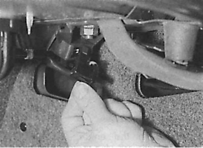
5. Unscrew the lower screw securing the decorative cover of the instrument cluster.
6. Remove the ashtray.
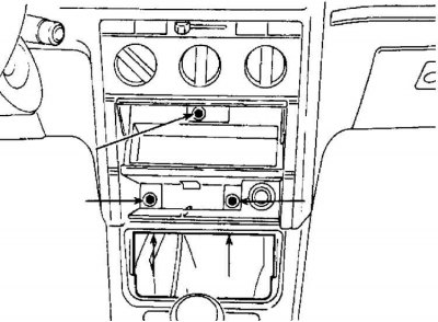
7. Unscrew five screws (indicated by arrows) center console mounts.
8. Pull the console forward and remove the connectors from the clock, cigarette lighter and switches.
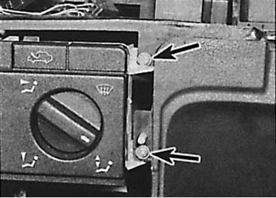
9. Unscrew four screws (indicated by arrows) control unit mounts and remove electrical connectors and control cables.
Installation
Sequence of installation of heater control cables
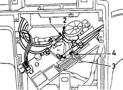
Heater Vent Flap Control Cable Routing Directions
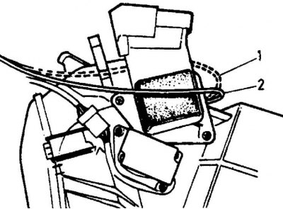
1 - wrong direction
2 - right direction
Installation is performed in the reverse order of removal. In this case, the control cables must be installed in a specific order.
Heater control unit (models since 1993)
Removal
1. Disconnect the negative cable from the battery.
2. Remove the central console.
3. Remove the ashtray and unscrew the two screws located at the bottom of the ashtray housing.
4. Remove the radio.
5. Unscrew the two screws from the top of the radio pocket and remove the pocket.
6. Using a lever, remove the locking plate from the upper corner of the central ventilation nozzle and unscrew the screw.
7. Unscrew the four screws located under the heater control panel.
8. Using a lever, remove the switches from the bottom of the central ventilation nozzle and unscrew the exposed screw.
9. Pull the casing forward and remove the connectors.
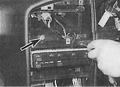
10. Unscrew two (indicated by an arrow) screws located on top of the heater control unit and remove the unit.
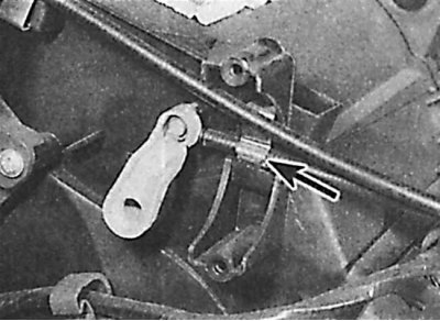
11. Release the clamps (indicated by an arrow) fastening the cable to the heater control unit.
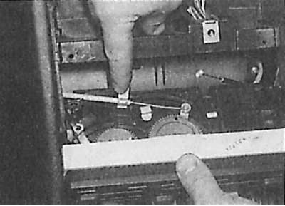
12. Remove the control cables and connector from the unit.
Installation
Installation is carried out in the reverse order of removal.
Heater fan
Removal
1. Unhook and remove the cover located under the instrument panel on the right side.
2. Remove the electrical wires attached to the fan housing.
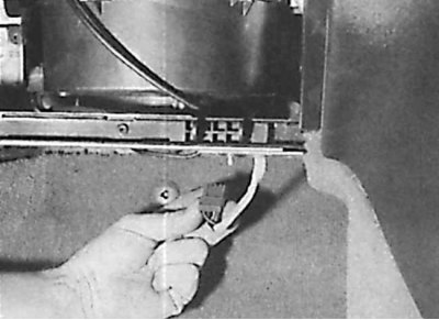
3. Disconnect the electrical connectors.
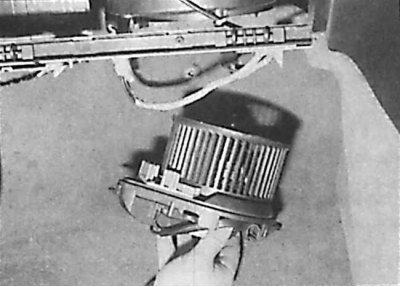
4. Remove the fan motor.
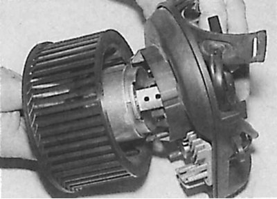
5. Remove the engine from the casing.
6. Unscrew the screws securing the housing to the body.
7. Remove the fan from the bottom. The fan is attached to the case with fasteners located behind the fan and screws around the perimeter.
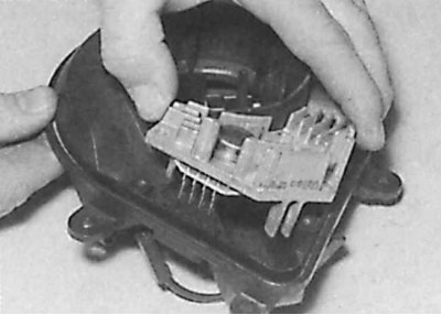
8. Remove the wire contact from the control unit, unscrew the two screws and separate the unit from the casing.
Installation
To install the fan, follow the steps in reverse order to the removal process, insert new fasteners into the housing at the bottom of the instrument panel.
Heater
Removal
1. Inside the engine compartment, install two clamps on the heating system pipes and disconnect them near the front bulkhead.
2. Drain the coolant from the heating system radiator.
3. Disconnect the ground wire from the battery.
4. Remove the instrument panel.
5. In the engine compartment, remove the fan air inlet deflector.
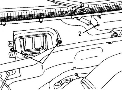
6. To access the heater mounting bolts, unscrew the screws (1) securing the plastic ventilation shield and the screws (2) securing the windshield wiper.
7. In the window sill, unscrew the three screws securing the heating system.
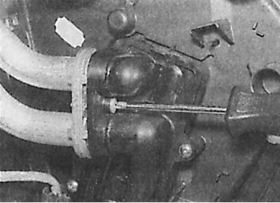
8. Inside the passenger compartment, unscrew the screw holding the heating pipes.
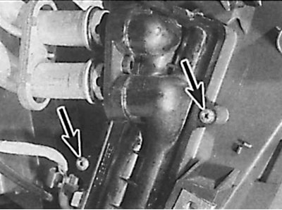
9. Unscrew the screws (indicated by arrows) radiator connections to the heater.
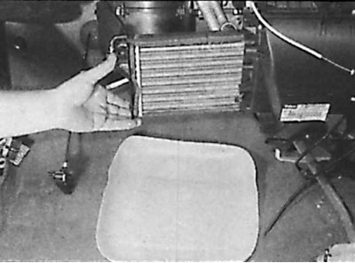
10. Remove the heater radiator.
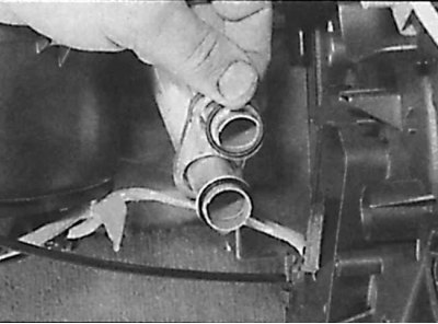
11. Remove the pipes directing air to the rear of the passenger compartment (in the picture – circular sealing rings on the pipes).
12. Unscrew the screw of the heating system holder on the console.
13. Remove the heating unit.
Installation
To install the heating system, perform the steps in reverse order to the removal process. Remember to install new seals, add coolant to the cooling system (to the required level) and removing air from the system.