



Table of contents: Multi-function steering column…🠇 Multi-function steering column…🠇 Switches on the instrument panel…🠇 Switches on the instrument panel…🠇 Heater Fan Switch 🠇 Front switches on the center console 🠇 Rear switches on the center console 🠇 Switches on the door 🠇 Switch on the door pillar 🠇 Ceiling mounted switches 🠇 Trunk light switch (sedan models) 🠇 Trunk light switch (combi models) 🠇 Electric sunroof switch 🠇
Multi-function steering column switches (models before 1993)
1. Remove the steering column covers.
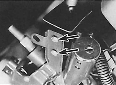
2. Unscrew two screws (indicated by arrows) fastening the switch to the steering column bracket.
3. Remove the switch and disconnect the electrical connector.
4. Installation is carried out in the reverse order of removal.
Multi-function steering column switches (models since 1993)
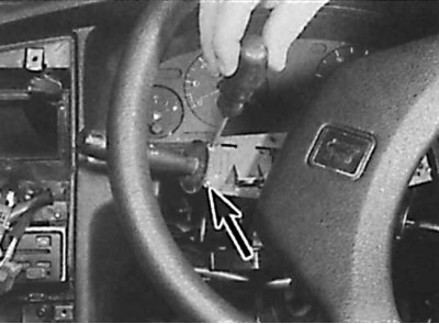
1. Remove the switch in the same way as previously described (see above). The difference is that access to the screws (indicated by an arrow) the switch is attached from the front of the switch.
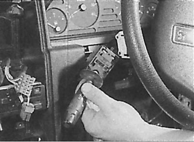
2. Remove the multifunction switch from the steering column.
Switches on the instrument panel (models before 1992)
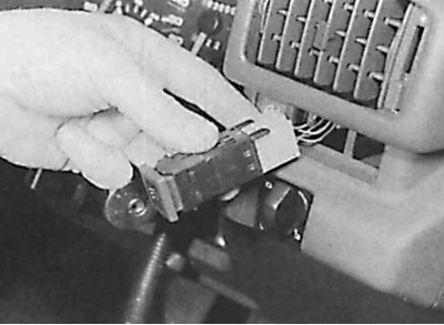
1. Using a thin screwdriver, release the plastic clips located on the sides of the switch and remove the switch from the instrument panel.
2. Disconnect the electrical connector from the switch.
3. When installing, connect the electrical connector to the switch and press the switch into the socket in the panel until it is secured with the clamps.
Switches on the instrument panel (models since 1993)
1. Removing the switch is done in the same way as described earlier (see above), except that the plastic fasteners are located at the top and bottom of the switch.
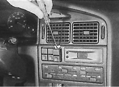
2. Remove the switch from the instrument panel.
Heater Fan Switch
The switch is integral with the heater control panel and cannot be replaced separately from the panel.
Front switches on the center console
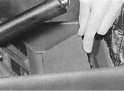
1. Using a thin screwdriver, remove the decorative trim from the base under the handbrake lever.
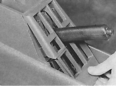
2. Using a thin screwdriver, remove the switch trim.
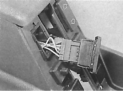
3. Using a thin screwdriver, remove the switch from the center console and disconnect the electrical connector.
4. Installation is carried out in the reverse order of removal.
Rear switches on the center console
1. Using a thin screwdriver, remove the rear ashtray from the center console.
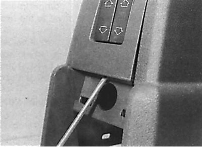
2. Using a thin screwdriver, remove the switch trim.
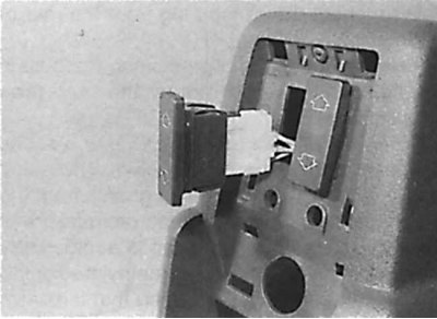
3. Using a thin screwdriver, remove the switch from the center console and disconnect the electrical connector.
4. Installation is carried out in the reverse order of removal.
Switches on the door
1. Using a thin screwdriver, remove the switch from the socket on the car door and disconnect the electrical connector.
2. Installation is carried out in the reverse order of removal.
Switch on the door pillar
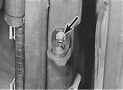
1. Open the door, then remove the rubber protective cover (indicated by the arrow) from the switch.
2. Unscrew the mounting screw and remove the switch from the door post.
3. Disconnect the electrical connector from the switch and tie a thin cord to the switch to prevent the wire from falling into the door frame.
4. Installation is carried out in the reverse order of removal.
Ceiling mounted switches
The switches are integral with the lights and cannot be replaced separately.
Trunk light switch (sedan models)
The switch is located in the suspension and is controlled by the trunk lid hinge.
1. Open the trunk lid.
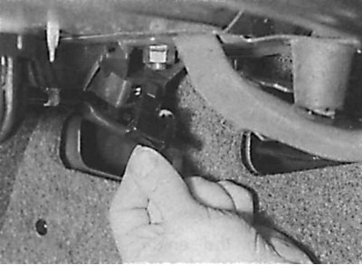
2. Release the brackets and remove the switch from the suspension.
3. Disconnect the electrical connector and remove the switch.
4. Installation is carried out in the reverse order of removal.
Trunk light switch (combi models)
The luggage compartment light is controlled by a tilt-sensitive switch located inside the tailgate.
1. Open the back door.
2. Remove the screws and remove the plastic trim from the inside of the rear door.
3. Working around the perimeter of the rear door carpet trim, release the fastening brackets and remove the rear door carpet trim.
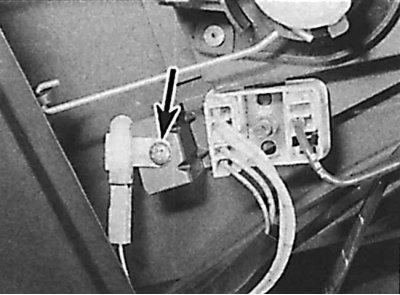
4. Unscrew the screw (indicated by the arrow), securing the switch to the rear door.
5. Disconnect the electrical connector and remove the switch.
6. Installation is carried out in the reverse order of removal.
Electric sunroof switch
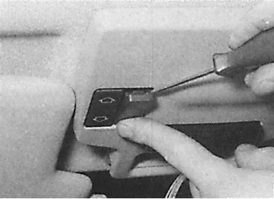
1. Using a thin screwdriver, remove the locking plate (located next to the sunroof switch) from the overhead console.
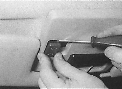
2. Push the switch out through the hole formed after removing the locking plate and disconnect the electrical connector.
3. Installation is carried out in the reverse order of removal.