



Table of contents: 5.1.1. Removal and installation 🠇 5.1.2. Cleaning and overhauling the…🠇 5.1.3. Carburetor adjustment 🠇
5.1.1. Removal and installation
The following text describes in general the work with all carburetors, regardless of the model they are installed on.
- Disconnect the battery.
- Disconnect the connecting hose with the air filter from the carburetor inlet fitting.
- Disconnect the throttle cable from the carburetor.
- Drain the engine coolant to at least the carburetor level. The base of the carburetor is washed with cooling liquid to heat the air-fuel mixture.
- Disconnect the water hose from the carburetor.
- After loosening the two clamp screws, disconnect the choke cable from the carburetor.
- Disconnect the vacuum hose from the carburetor.
- Disconnect the fuel hose from the carburetor. Close the end of the hose to prevent dirt and foreign objects from entering.
- Disconnect the electrical wire from the idle air control valve solenoid contact.
- Unscrew the carburetor from the intake manifold. Immediately cover the intake manifold opening with a clean cloth to prevent foreign objects from entering the engine.
The carburetor is installed in reverse order.
5.1.2. Cleaning and overhauling the carburetor
After disassembling the carburetor for cleaning or overhaul, all gaskets must be replaced. Rinse the float chamber with clean gasoline, using only a lint-free cloth for wiping.
When overhauling a carburetor, the following precautions must be observed:
- Never use needles, pieces of wire, etc. to clean out jet holes, channels, or other openings, as this may cause the holes to become uncalibrated.
- When replacing jets, install jets only with the required hole sizes. Jets are selected based on engine type, and installing a jet with a larger bore will not yield any gains in power, throttle response, etc., unless other specific jets are also replaced. The desired success can only be achieved by testing the engine on a dyno.
- When replacing, install only parts supplied by the vehicle manufacturer or Solex.
- Do not process aluminum parts with sharp tools. Do not overtighten the screws and, above all, ensure that the screws are properly seated in the threads before tightening them. Aluminum threads are easily stripped, and if the seal is not complete, foreign air can penetrate, which negatively affects operation, especially in idle mode.
- To unscrew the jets, use only screwdrivers with a sharp tip. Do not damage the jet splines, as this may damage the jet bore.
- When removing the float, do not bend its tongue, as this will disrupt the float level adjustment. Store the float in a safe place. To check the float chamber needle valve, insert the valve and blow into the fuel inlet. Air should not be blown into the hole. When releasing the needle, air should pass freely.
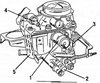
Figure 97. View of the carburetor from the side of the electromagnetic idle shut-off valve. 1. Idle air control solenoid valve; 2. Mixture adjustment screw (with a cork seal); 3. Fixed screw for adjusting the CO content; 4. Fuel nipple with inserted mesh filter; 5. Engraving of carburetor type designation
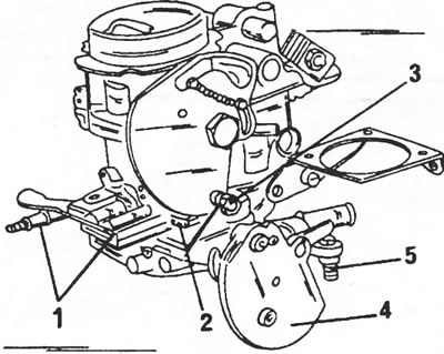
Figure 98. View of the carburetor from the throttle lever side 1. Accelerator pump linkage system; 2. Throttle valve gap adjustment screw; 3. Connecting the air damper cable; 4. Throttle segment; 5. Throttle stop screw (idle speed adjustment)
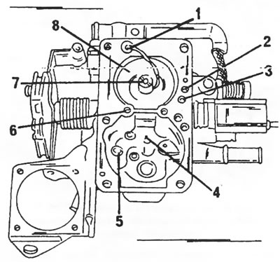
Figure 99. Carburetor - top view 1. Injection pipe; 2. Idle fuel jet; 3. Idle air jet; 4. Main jet; 5. Accelerator pump inlet valve; 6. Economizer jet; 7. Air correction jet with mixing tube; 8. Air funnel
In Figures 97 - 99, various types of carburetors are shown to clearly illustrate the location of parts during repair.
Complete disassembly of the Solex carburetor is carried out as follows:
- Loosen the carburetor cover screws and remove the cover with the gasket. The gasket must be replaced.
- Unscrew the float chamber needle valve from the cover.
- Unscrew all the jets using the drawings.
- Disconnect the accelerator pump rods, unscrew the accelerator pump cover from the side of the carburetor and remove the cover with the membrane and spring.
- Remove the float shaft with the float from the carburetor. The float axis is knocked out from the inside out.
- Remove the idle speed adjustment screw, CO content adjustment screw and idle speed shut-off electromagnetic valve from the side of the carburetor.
- The carburetor is assembled in reverse order. During assembly, certain adjustments must be made as described in section 5.1.3.
- It is especially necessary to pay attention to the following points:
- Adjust the float level as described in section 5.1.3.
- If the injection tube was removed, replace the gasket.
- If the accelerator pump was removed, reassemble using Figure 100. Ensure that the conical springs are installed correctly. Place the membrane into the carburetor body with the flat side and tighten the cover with the membrane in this position. Adjust the accelerator pump as described below.
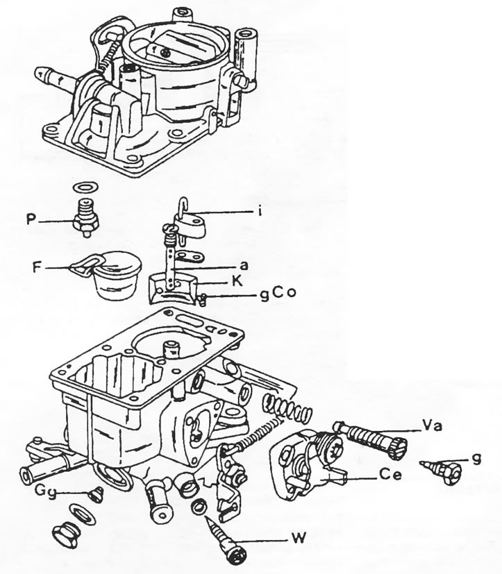
Figure 100. Assembly drawing of the Solex PBSIA carburetor.
5.1.3. Carburetor adjustment
Adjusting the float level
To adjust the float of the 34 PBISA carburetor, a special template is required. Turn the lid over and place the template on the lid (the gasket is applied) and on the float, as shown in Figure 101. The float should touch the edge of the template, with a tolerance of 1.0 mm.
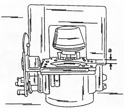
Figure 101. Measuring the float level using a special template. The gap "a" should not be more than 1.0 mm.
If there is no template, turn the lid over and use a depth gauge to measure the size from the surface of the lid to the top edge of the float. The size should be 38 mm.
Idle speed adjustment
The idle speed of the small engine and the engine with a working volume of 1971 cm3 with a power of 78 hp is 800+50 rpm. The idling speed of an engine with a displacement of 1,971 cm3 and a power output of 85 hp is 900±50 rpm. All models are adjusted in the same way. Figure 102 shows the location of the carburetor in the engine compartment. Adjustment can be made using this drawing.
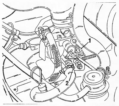
Figure 102. Idle speed adjustment screws. The screw (1) is the throttle stop screw
Dampers, screw (2) - mixture adjustment screw.
Before checking and adjusting the idle speed, the ignition timing and valve clearances must be adjusted. Adjustment requires a rev counter and a CO meter, but less precise CO adjustment can be made without a meter.
With a device for measuring CO content
- Connect the RPM meter and CO meter according to their operating instructions.
- Warm up the engine until the fan turns on and off.
- Check if the air damper is fully open.
- With the engine running, take readings from the RPM meter.
- Take readings from the CO measuring device.
- Make adjustments:
- Turn the throttle adjustment screw (1) in Figure 102 until the specified idle speed is set.
- To adjust the CO content, turn the screw (2) in Figure 102. The screw is located under a seal, which must first be removed with a sharp tool. After this, set the adjusting VIN to a position where the CO value is between 0.5 and 2.5% on engines with a displacement of 1.8 liters or between 1.0 and 2.0% on higher-power engines with a displacement of 2.0 liters.
- Check the RPM readings again and make further adjustments if necessary. The same applies to the regulation of CO levels.
- Install a new seal (white) in the hole of the adjusting screw. Be sure to press down on the filling.
Without a CO2 meter
- Adjust the idle speed as described above.
- After this, insert the screwdriver again into the throttle stop screw (1) in Figure 102 and increase the speed by 50 rpm.
- Set the maximum speed by turning the mixture control screw.
- Repeat the last two working operations until the highest revolutions are obtained when turning the screw (2).
- Turn the screw (2) until the speed drops to 800 or 900 rpm, depending on the engine type.
- close the filter housing, remove the cover and take out the filter element.
- The filter element is replaced every 20,000 km.
- The air filter is installed in reverse order. In this case, it is necessary to install the hose clamps correctly and tighten them well.
Original text is located at [peugeotbook.ru]