



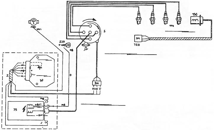
Figure 103. Connection diagram of the elements of the transistor ignition system. 5 Ignition distributor; 50 Ignition coil; 75 Ignition module; 114 Spark plugs; 130 Top dead center sensor; 229 Ignition switch; 720 Diagnostic connector
In this ignition system, the distributor breaker contacts are replaced by a magnetic sensor, which transmits ignition pulses to the electronic ignition module (75). The pulses are generated by the rotation of a four-cornered sprocket in the pulse sensor, meaning that one corner of the sprocket corresponds to one cylinder. The module generates and interrupts voltage for the primary circuit of the ignition coil (50). This induces high voltage in the secondary circuit of the ignition coil and a spark in the spark plug corresponding to the current position of the ignition distributor. The remaining elements of the ignition system are similar to those of a conventional ignition system.
The ignition coil is designed specifically for this ignition system and converts the voltage in the primary winding into voltage in the secondary winding of the value required for the operation of the ignition system.
When working with the ignition system, the following precautions must be observed:
- When adjusting the idle speed, use only an idle speed meter designed for electronic systems. Before connecting, make sure that the device being connected is suitable.
- Do not use a quick charger to start the engine when the battery is discharged.
- When carrying out electric welding work, disconnect the battery. This must be done also because of the alternator.