
2. Turn the box over and remove the bolts with special washers securing the pallet. If not already done, you will first need to unscrew and remove the nuts securing the exhaust pipe bracket to the box. When removing the bolts, pay attention to the fact that 3 of them are longer than the rest, and remember the position on the box crankcase.
3. Unscrew and remove the three bolts securing the strainer, paying attention to the rubber seal between the filter and the crankcase.
4. Remove the 4 bolts securing the oil seal support washer to the final drive (clutch side). Mark the washer and crankcase so that it can be reinstalled correctly later, and carefully remove the washer, being careful not to lose the shims. Remove all shims and set aside in one place. The sealing ring between the lock washer and the crankcase, and the final drive oil seal in the washer, must be replaced during assembly.
5. Remove the 4 large and 4 small bolts securing the differential box to the gearbox housing and remove the differential box. If she's bad "goes", you can tap it with a soft-faced hammer. The differential can be pulled out of its box, but be sure to set aside the tapered roller bearing outer races with their bushings. Here we do not consider the differential bulkhead. If it is defective or badly worn, it should be replaced as an assembly or have it repaired by a specialist.
6. Remove the nut and locking screw securing the speedometer drive. Remove drive.
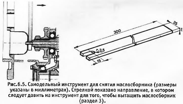
7. An oil sump is installed in the box crankcase on the clutch side, from which a short tube extends to the output shaft. Its task is to direct oil into the shaft to lubricate the 1st gear driven gear through special bores. To remove the oil sump, a special tool is required, which you can make yourself according to B / fig. 6.5. The same figure shows how to use the tool.
8. Engage reverse gear and carefully drive out the cylindrical pin that secures the reverse fork to its stem. While holding the reverse idle gear engaged, engage 1st gear. After that, the drive, input and output shafts will be locked, which will allow you to loosen the nut on the end of the output shaft (this nut must be replaced at assembly). Immediately install a new nut on the end of the shaft and tighten it until a small moment (about 5 kg m). This will allow you to check the axial movement and clearances before removing the output shaft.
9. Unscrew and remove the 3 bolts securing the triangular plate holding the input shaft ball bearing.
10. The outer ring of the ball bearing has a groove for installing a special puller. If you do not have a special puller, the ball bearing can be removed in the following way. Remove the retaining ring and the Belleville washer behind it from the end of the input shaft. Note that the outer rim of the Belleville washer is in contact with the bearing inner race and the inner rim is in contact with the circlip. Carefully drive the drive shaft inward towards the gear clusters. In this case, the ball bearing, standing at the opposite end of the input shaft, protrudes slightly outward. While holding the bearing in the extended position with a screwdriver in the groove on its outer ring, have an assistant carefully hammer the input shaft back into the crankcase. Repeat this procedure until you can pull the ball bearing out. Be careful not to apply too much force to the bearing. The outward movement of the bearing must be very small each time.
11. After removing the bearing, disengage the reverse idle gear. Unscrew the 2 bolts securing the cover of the middle bearing of the input shaft, and remove the cover. If the roll pins fall out when it is removed, they must be reinstalled in the crankcase.
12. Compress the retaining ring at the junction of the drive and input shafts and disengage the shafts. Pay attention to the fact that there is a rubber washer in the hole of the input shaft, against which the end of the input shaft must abut. This washer must be replaced during reassembly. Pull both shafts out of the crankcase and move the gear rods to the neutral position.
13. Now you need to check the axial movement and clearances of the secondary shaft in order to determine which of its parts need to be replaced.
14. Axial movement. The easiest way to determine the axial movement is with a dial gauge mounted on the crankcase so that its button rests on the end of the secondary shaft, and the roller is parallel to the shaft axis. Move the secondary shaft to the stop in each of the directions along its axis and measure the axial displacement of the shaft. Alternatively, you can use a depth gauge, but since the maximum allowable axial movement is only 0.5 mm, a very accurate depth gauge is required so that it can be used to assess the condition of the output shaft ball bearing, which determines its axial movement. If the axial movement is too large, the bearing and its circlip must be replaced and the axial movement checked again. If it again exceeds the permissible limits, it is necessary to replace the gearbox housing or (depending on the condition of the box) the whole box set.
15. Clearances of driven gears. Each of the output shaft gears has an operating clearance to allow it to rotate on the hub when not locked by the synchronizer in order to rotate the shaft. First check that the inner ring of the needle roller bearing (see b/fig. 6.6), located at the same end of the shaft as the nut touched the 4th gear hub, and the lock nut touched the needle bearing inner race. Using feeler gauges, measure gaps J1, J2, J3 and J4, which should be 0.2-0.35 mm. If the values obtained exceed these limits, the driven gear bushings must be replaced.

16. After that, the centralization of the synchronizers should be checked, however, this check does not make sense if the axial movement of the secondary shaft and the clearances of the driven gears do not go beyond the specified limits. However, if it is intended to replace the gearbox housing or output shaft, shift forks, rods or locking plungers, this check should be made after the gearbox is assembled.
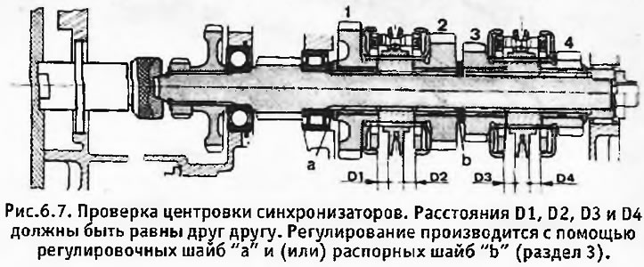
17. With the gear shift forks in the neutral position, the synchronizer rings must be centered with respect to the synchronizer cones. To check this, measure the distances D1, D2, D3 and D4 shown in B / fig. 6.7. These distances must be equal to each other with the maximum opening of the corresponding parts. A tool is provided to check these distances "Peugeot", however, instead, you can use a homemade tool 9 mm wide, which is inserted into the appropriate gaps.
18. Before carrying out the check, the output shaft should be slightly loaded towards the end nut. There is also a special tool for this "Peugeot", shown in the attached drawing, but a block of wood with a wedge can be used instead. In order to properly load the shaft, a special tool is tightened by hand (shown in the picture). Check that all forks and stems are in the neutral position (checked by the position of the blocking plungers).
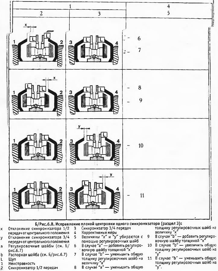
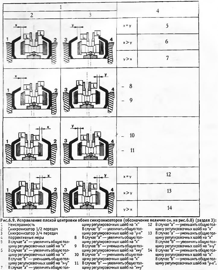
19. Alternately insert a feeler gauge between each of the synchronizer cones and the synchronizer hub adjacent to it, being careful not to apply any force. Ideally, the feeler should fit between the cone and hub in all four cases, but if it does not, refer to B/fig. 6.8 and 6.9, which show 8 possible options and the necessary corrective measures. Adjustment is made using shims "A" and spacer washer "b", shown in the same figures. At the stage of disassembling the box, it is enough just to remember the thickness of the adjusting parts you need in order to choose them correctly during assembly. After that, you will have to check the gaps again to make sure everything is in order.
20. Pull out the wooden block with the wedge used to load the secondary shaft, and turn on 4th gear. Carefully knock out the cylindrical pins from the yoke on the 3/4 gear shaft and the shaft of the reverse idler gear. Remove the axle and intermediate gear from the gearbox and return the rods to the neutral position.
21. Unscrew the bolts of the connection type "banjo" at the point of attachment of the outer lubrication tube to the gearbox and remove the tube and bolts with washers. Unscrew the 4 bolts securing the gearshift cover to the gearbox housing, and carefully remove the cover, being careful not to lose the balls and springs of the detents. Remove balls and springs from crankcase. Remove old cover gasket (must be replaced with a new one during assembly).
22. Engage the reverse gear lock and carefully turn the stem up. In the process of this, the retainer ball should pop out. Grab it so it doesn't get lost and remove the spring. Knock out the roll pin securing the retainer to the reverse rod and remove the retainer and stem.
23. Engage 2nd gear and knock out the cylindrical pin that secures the 3/4 gear Retainer to its stem. Knock out the roll pin securing the 1/2 gear fork to the stem, but leave a punch in the stem hole and set the fork to neutral. Rotate the 3/4 gear stem up 1/4 turn to prevent the lock pin from falling out.
24. Remove both rods, 3/4 gear detent, both forks and lockout plungers.
25. Remove the nut from the end of the output shaft (from the casing of the gas distribution mechanism). From the other end of the shaft (clutch side) remove the circlip, belleville washer, speedometer drive worm, shim, and reverse driven gear.
26. Working through the hole in which the differential stood, unclench the retaining ring that secures the outer ring of the secondary roller bearing of the secondary shaft and, using a hammer with a soft head, protrude the shaft out (towards the clutch). Remove shaft. Pull the synchronizer and gear assembly out of the crankcase and note the position of the spacers and shims. Do not disconnect synchronizers from their hubs - if they are not to be replaced, they should be installed in the original order.
27. On this, the disassembly of the box can be considered complete. Further disassembly (removal of the ball bearing of the secondary shaft or the bushing of the input shaft) may only be required if the condition of the relevant parts is poor. If they are in order, it is better not to disassemble the box further. Keep in mind that the replacement of the input shaft sleeve must be carried out by a specialist, because. alignment of the hub with the other two bearings is critical.