
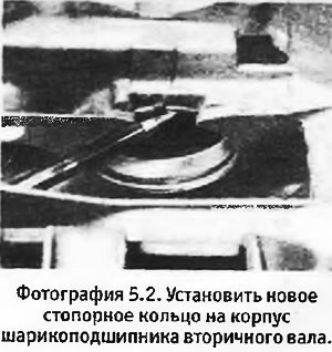
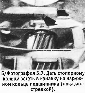
2. Place the box crankcase on the desktop. Install a new circlip into the groove on the output shaft ball bearing housing (see photo).
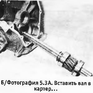
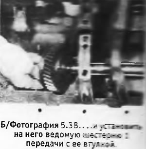
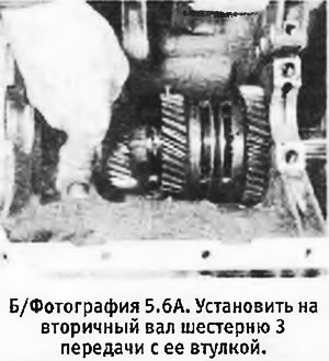
3. Install the shims on the output shaft (next to the roller bearing inner ring). The thickness of these washers was calculated during the disassembly of the box. However, if there is too much side play, or if some of the washers have been lost, or if you have replaced the driven gear bushings, gearbox housing, intermediate shaft or forks, rods or retainers, a 0.75 mm thick shim should be installed. Later, you can check and adjust the washer thickness, but you will already have something to start with. Partially insert the shaft into the box and install the 1st gear driven gear on it along with its bushing (see pictures).
 |  |
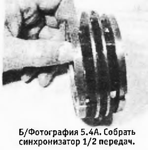
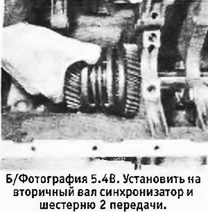
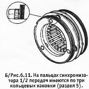
4. Assemble the 1/2 gear synchronizer and check that the alignment marks made during disassembly match on its hub and coupling (see photo). Install the synchronizer on the output shaft. The locating pins on the synchronizer, marked with three grooves, must point towards the 1st gear (see B/fig.6.11). Install the 2nd gear gear with its bushing on the shaft (see photo).
 |  |
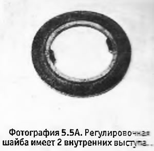
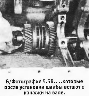
5. Install the shim on the shaft (see pictures). As in the previous case, its thickness had to be determined during the disassembly of the box. However, if, for the reasons given in paragraph 3, you are in doubt about the thickness of the washer, you should install a 2.60 mm thick washer and then correct its thickness after checking the clearances and alignment of the synchronizers.
 |  |
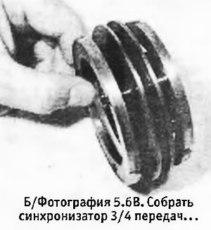
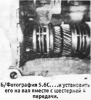
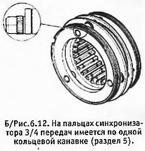
6. Install the 3rd gear gear with its bushing on the shaft (see photo), install the cones on the 3/4 gear synchronizer and check that the alignment marks on the hub and synchronizer sleeve match each other (see photo). Install the synchronizer on the output shaft. The dowel pins on this synchronizer are marked with a single groove and should face the 3rd gear (see b/fig. 6.12). Install the 4th gear with its bushing (see photo).
 |  |
 |  |
7. Carefully drive the assembled secondary shaft into the box crankcase. When the ball bearing reaches its retaining ring, the latter must be opened with pliers to remove the retaining rings and continue to drive the shaft into the crankcase. Let the circlip fit into its groove on the outer ring of the ball bearing and release it (see photo).
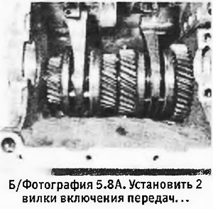
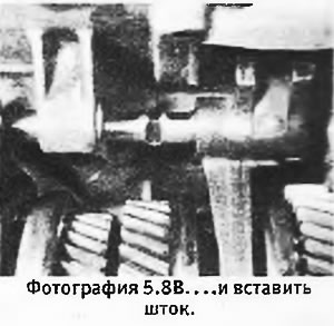
8. Install the 1/2 and 3/4 forks into the grooves on the respective synchronizers (see photo). Insert the stem of the 1/2 gear fork into the hole in the 3/4 gear fork and position it so that the notch of the locking plunger is in line with the axis of the plunger hole. Install the plunger in the hole so that it rests on the 1/2 gear stem and check that it does not go into the hole in the 3/4 gear stem (see pictures).
 |  |
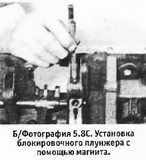
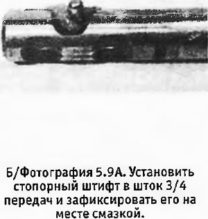
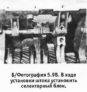
9. Position the 3/4 gear stem so that the 2 chamfers on it are facing up and install the locking pin in the hole provided for it and lock in place with grease (see photo). Install the stem into the crankcase while placing it on the selector block (see photo). Rotate the stem 3/4 turn towards the shift cover and hammer new roll pins into place in the stems, forks and selector block (see pictures).
 |  |
 |  |
10. Install the second blocking plunger in the hole provided for it.
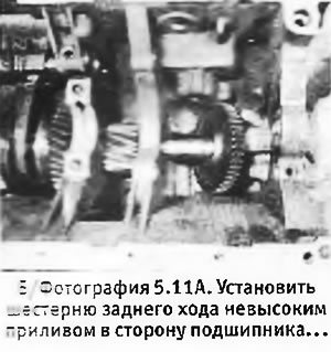
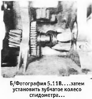
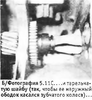
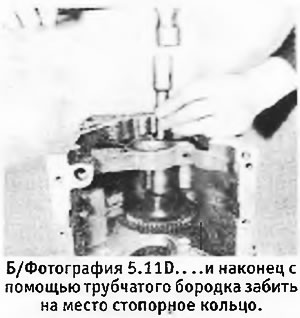
11. Install the reverse gear on the output shaft so that a low tide on it touches the inner race of the ball bearing, and then install the speedometer worm wheel (see pictures). These 2 pieces are held in place by a Belleville Washer, which must be installed with its outer rim in contact with the worm wheel. Check that the washer is slightly compressed after installing the retaining ring. If this does not happen, it is necessary to install an adjusting washer between the reverse gear and the speedometer worm wheel, choosing its thickness so that the washer is compressed. Having achieved the desired result, install the retaining ring on the end of the shaft and, using a tubular beard, drive it into the groove intended for it (see pictures).
 |  |
 |  |
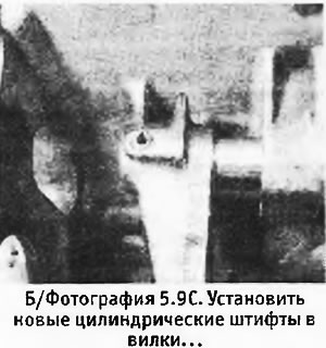
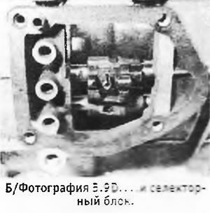
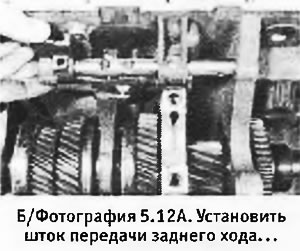
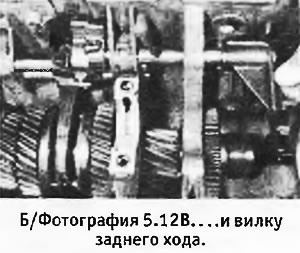
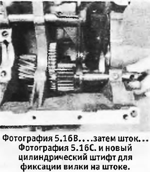
12. Install the reverse gear rod into the hole in the crankcase intended for the rod bearing, so that the chamfers on it look towards the gearshift cover, and install the fork (see pictures). If the selector block was removed, install it on the stem and fix it with a new cylindrical pin.
 |  |
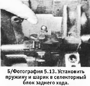
13. Rotate the stem so that the selector block is facing up and install the spring and ball in their hole in the block (see photo). Compress the spring by lowering the block and move the stem to the neutral position.
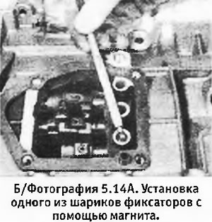
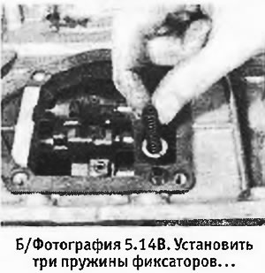
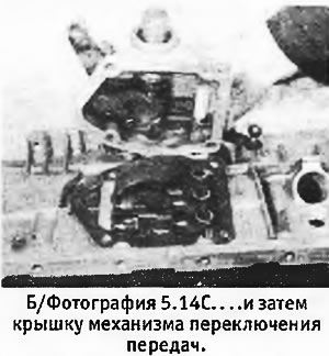
14. Install three springs with balls in the rod retainers and check that the centering lug (cylindrical pin) was in its place on the surface on which the gearshift cover rests. Install a new gasket and install the cover, securing it with 4 bolts with new washers (see photo). Tighten the bolts to the correct torque. Check the operation of the rods of 4 translational gears (do not touch the reverse gear yet) and then bring the rods to the neutral position.
 |  |
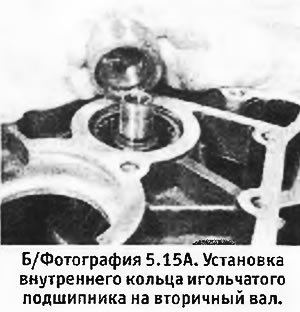
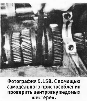
15. Install the secondary shaft needle bearing inner race. Early models have a washer that must be installed prior to installing the inner ring, but later models have a notch in the ring instead. The ring must be installed so that the recess in it touches the bushing of the driven gear 4th gear (see photo). Drive the ring into place with a suitable tubular beard (e.g. socket wrench heads) and install a new lock nut, tightening it at this stage to a slight torque (about 0.5 kg m), because it is also necessary to check the alignment of the driven gears on the output shaft. If the test shows that (for example, due to the installation of new parts) it is necessary to center the gears on the shaft, you will have to disassemble the box to install the appropriate shims or spacer (see photo).
 |  |
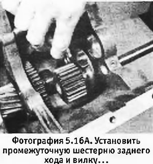
16. After the gears are centered (or if they don't need to be centered at all), install the reverse idle gear shaft and the reverse gear itself. Install the reverse fork on the gear and secure it to the stem with a new roll pin (see pictures).
 |  |
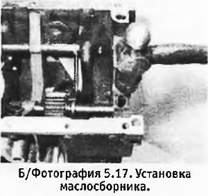
17. Apply some sealant to the contact rim of the oil sump and install it in its place in the crankcase. Carefully hammer it into place, making sure that the oil supply tube is aligned with the end of the output shaft (see photo).
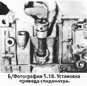
18. Install a new O-ring on the speedometer drive and apply some grease to it. Install the drive into the crankcase, engaging the worm with the gear, and align the holes for the mounting screw. Install the machine screw with its locknut, but do not tighten them until the power unit is installed back on the machine and the speedometer cable is connected (see photo).
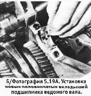
19. Install new half shells in the driven shaft bearing and its cover (see photo). Install a new rubber washer in the driveshaft halves coupling. Install a new retaining ring on the drive shaft (see photo). Check that the centering necks of the liners are installed in the main crankcase and lubricate the liners.
 | 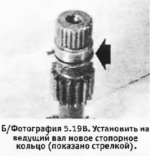 |
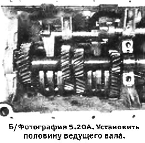
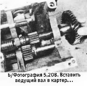
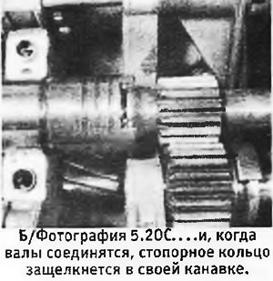
20. Install half of the drive shaft into the crankcase (see photo) and insert the drive shaft through its bearing, being careful not to damage the bearing surface (see photo). Position the coupling with the notch up and insert the drive shaft into it. Compress the circlip at the end of the shaft and push it inward until the circlip snaps into the groove on the shaft (see photo).
 |  |
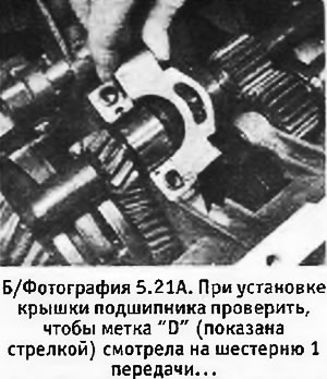
21. Install the bearing cover with the mark "D" gear side (see photo). Insert 2 mounting bolts with new flat washers and tighten them to the correct torque (see photo).
 |  |
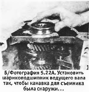
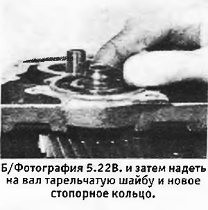
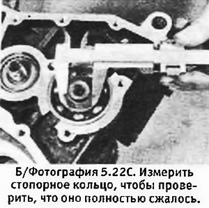
22. Install the ball bearing in its housing, making sure that the groove for the puller is outside of the housing (see photo). Hammer the bearing into place using a tubular beard, abutting it against the inner race of the bearing. Fit a new Belleville washer and install a new circlip on the shaft end. Compress the ring in the groove on the shaft and check that its outer diameter does not exceed 22.6 mm (see pictures).
 |  |
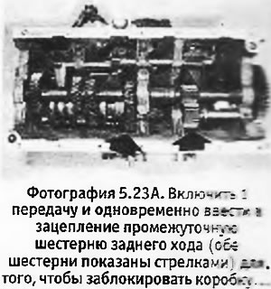
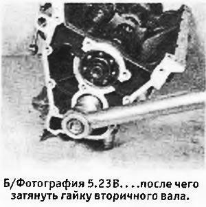
23. Engage 1st gear and simultaneously engage the reverse idle gear to lock the box. Tighten the output shaft nut to the correct torque (see pictures).
 |  |
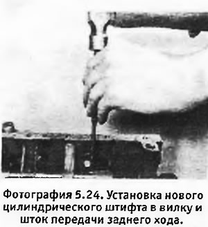
24. Return the 1st gear to neutral and install a new roll pin into the yoke and reverse gear shaft (see photo). Turn on all gears one by one (including reverse gear) and check that they turn on and off smoothly and without jerks.
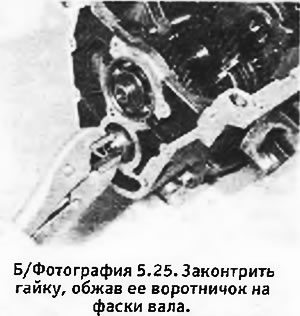
25. Lock the output shaft nut by crimping its collar on the chamfers of the shaft with pliers. Do not use a hammer for this purpose, because. you can damage the shaft or its bearings (see photo).
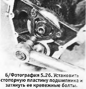
26. Install the triangular ball bearing retainer plate and tighten its 3 fixing screws to the correct torque (see photo).
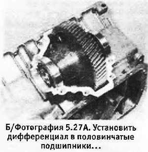
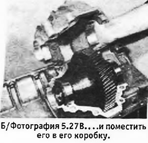
27. Install the outer races on the differential tapered bearings. Install the differential in its place in the gearbox (see photo). Cover the contact surfaces of the differential box and gearbox housing with sealant and install the gearbox on the housing (see photo). Install 4 long and 4 short bolts with new spring washers, do not tighten them at this stage.
 |  |
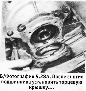
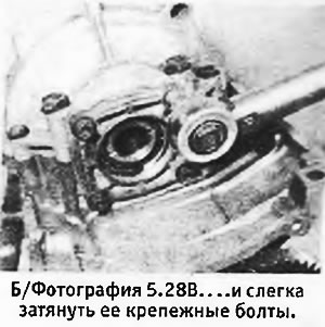
28. Check that there is no oil seal on the end cover of the differential, and install the cover on the differential box, tightening the 4 mounting bolts to a small moment (about 1 kg m) (see pictures). After that, tighten to a small moment (0.5 kg m) 4 small bolts (diameter 8 mm) in the differential box. After tightening these bolts, unscrew the end cap bolts and remove the end cap. Check that the outer ring of the bearing sits down on the rollers.
 |  |
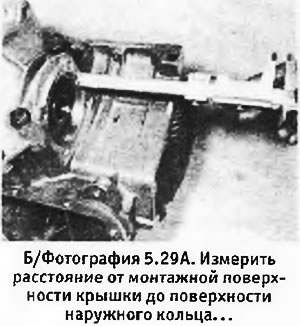
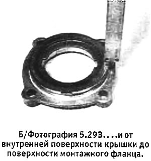
29. When assembling, it is necessary to give the tapered bearings a slight preload, which is achieved by installing shims under the end cover. To calculate the required thickness of the gaskets, some measurements must be taken. Using a depth gauge or vernier caliper, measure the distance from the mounting surface of the cover to the surface of the outer ring while slightly pushing the differential inward (see photo). Then measure the distance across the bearing cover from the surface adjacent to the mounting flange to the surface which, after assembly, will touch the bearing outer ring if there is sufficient protrusion (see photo). Subtract the second value obtained from the first, which will give you the distance between the cover and the bearing ring. Add 0.2 mm to the resulting figure, and you will get the thickness of the shims necessary to obtain the desired preload.
 |  |
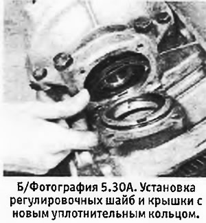
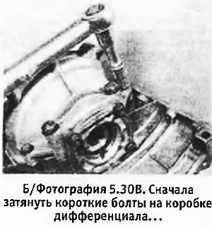
30. Install a new o-ring coated with grease on the cover and apply sealant to the contact surfaces of the cover. Install shims of the correct thickness on the outer race of the bearing. Install cover on differential box (see photo). Insert the bolts with new spring washers and tighten the bolts to the correct torque in the following sequence:
- A. short bolts with a diameter of 8 mm in the differential box
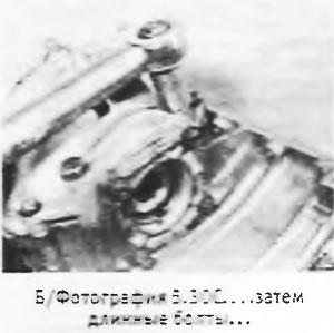
- b. long bolts with a diameter of 10 mm in the differential box
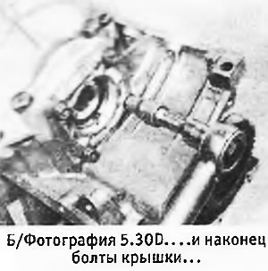
- V. end cap bolts.
 |  |
 |  |
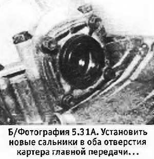
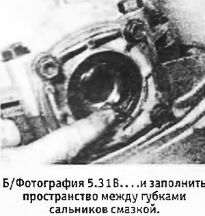
31. Apply a little grease to the new oil seals and install them in both holes on the final drive housing (see photo). Using a suitable beard, carefully hammer the seals inward until they fit on the flange in the holes. Before installing drive shafts (after the power unit is installed back on the machine) it is necessary to fill the space between the lips of the seals with grease (see photo).
 |  |
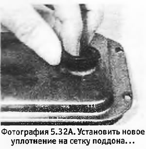
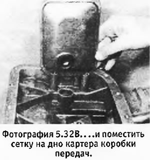
32. Install a new rubber bushing on the oil pan mesh (see photo). Install the mesh in its place on the bottom of the gearbox housing (see photo). Tighten the three mesh fixing bolts to the correct torque.
 |  |
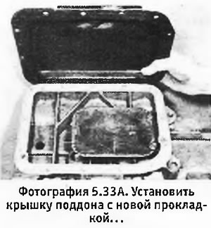
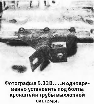
33. Check that the contact surfaces of the box crankcase and sump cover are clean and undamaged. Install new gasket and pan cover (see photo). When installing bolts, use special locking plates. Make sure the 3 long bolts holding the exhaust pipe bracket are in place (three middle bolts on the rear edge of the sump cover). Tighten the bolts to the correct torque. Install a new sealing washer on the sump drain plug and tighten the plug to the correct torque.
 |  |
34. Oil dipstick tube and external oil tube are best installed after the box is connected to the engine (see next section).