
Anti-Lock Braking System (Bendix ABS)
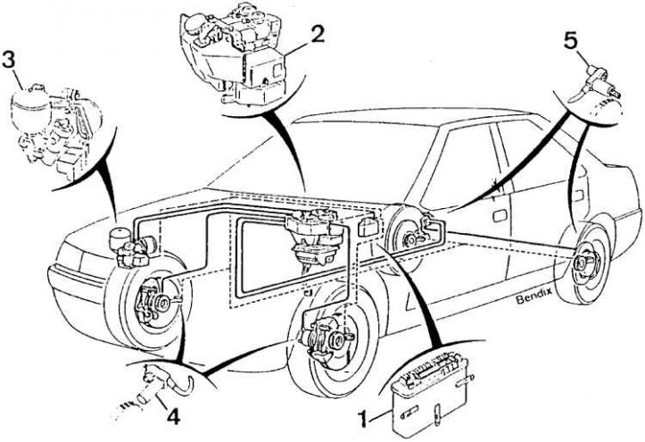
1 - electronic control module, 2 - hydraulic assembly, 3 - electrically driven pump assembly, 4 - front wheel sensors, 5 - rear wheel sensors
Functional diagram of Bendix ABS
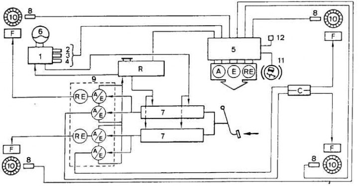
1 - pump assembly with electric drive, 2 - 16.0 MPa sensor, 3 - 18.0 MPa sensor, 4 - 9.0 MPa sensor, 5 - electronic control module, 6 - pressure accumulator, 7 - pressure transmitters, 8 - sensors, 9 - hydraulic unit, 10 - gears, 11 - signal light, 12 - control connector (M897), A / E - electrically controlled intake-exhaust valves, F - brakes, R - brake fluid reservoir
Principle of operation
During heavy braking, the wheel may skid on the surface. The peripheral speed of the wheel in this case is less than the speed of the car.
Slip minimum (0%), when the wheel rolls freely, and the maximum (100%), when the wheel is locked. Braking efficiency is greatest when the slip ratio is 15%, which allows you to maintain good vehicle stability and controllability.
The role of ABS is to limit the pressure in the brake system so that the value of the slip coefficient is approximately equal to the recommended value.
The action of this system must be immediate and independent for each wheel. The system must respond immediately to every change in road surface and vehicle load.
Design
ABS consists of electronic and hydraulic elements. It includes the following parts.
Placed in place of the classic brake master cylinder, a hydraulic assembly that has two pressure transmitters feeding two independent circuits of the system type "X" and six electronically controlled pressure modulation valves. Four of them receive electrical signals sent by the control module and modulate the pressure in the brake circuit. The other two valves protect against sudden pressure changes in the front brakes so as not to impair the performance of the car.
Four sensors (one for each wheel), which send data on the instantaneous speed of each wheel to the control module.
Electronic control module (placed on the wall of the front left fender), which, based on data from sensors, controls the electric valves of the hydraulic unit. This module is also equipped with an auto-diagnostic tool that informs the driver about the occurrence of a malfunction.
An electrically driven pump assembly that creates the necessary pressure in the brake system.
Three different types of ABS can be applied depending on the vehicle model.
Bendix system with integral ABS
This system was installed on some models until 1993 as standard equipment. The system is adapted instead of the conventional system, the brake pedal action is transferred to the hydraulic control unit, which replaces the brake master cylinder and vacuum booster in the conventional brake system.
The system operates at very high pressure, typically between 158 and 183 bar, which is generated by an electric pump mounted on the modulator.
The system will continue to work even if the sensor installed on the vehicle wheel fails. In the event of a general failure, the control unit will return the system to normal braking.
Bendix system with optional ABS
The Bendix system with additional ABS is installed on some models, ABS is adapted in addition to the usual elements of the brake system.
The system uses the pressure generated by a conventional brake master cylinder and a vacuum booster.
The system will continue to operate in normal braking mode in the event of an ABS failure.
Bosch 2E system with optional ABS
The Bosch 2E system with optional ABS has been fitted to some models since 1993 and is similar to the Bendix with optional ABS.
Functioning
If one of the sensors registers the beginning of wheel blocking, then the control module acts on the corresponding electric valve, which closes and thereby maintains the required braking pressure (for this wheel).
If, nevertheless, complete blocking of the wheel occurs, then the electric valve connects the corresponding brake to the compensation tank and the pressure drops sharply. The wheel starts to turn again. This causes a change in the state of the electric valve, due to which the pressure rises again. This cycle is very fast (several times per second), and the whole process lasts either until the car stops, or until the pedal is released.
Control
ABS is equipped with a self-diagnosis device connected to the control module, which, in the event of a malfunction in the electronic part of the system, causes the warning light on the instrument cluster to light up. This light does not indicate the source of the problem. To accurately determine the cause of the malfunction, the following method should be applied.
1. Connect a switch between the tip marked M897 and ground.
2. Turn on the ignition and close the switch for 3 seconds. The control lamp on the instrument panel will light up.
3. Open the switch. The control lamp will light up once, which corresponds to the number 1 in the row of tens. Then the lamp goes out for 1.5 seconds and lights up twice, which corresponds to the number 2 in the series of units.
4. This signal should be interpreted as the number 12, which is the code for the start of the test.
Troubleshooting
The malfunction code is the number 51.
1. Close the switch for 3 seconds, the control lamp should light up.
2. When the switch is open, the control lamp lights up, for example, 5 times, which corresponds to the number 5 in the row of tens. The lamp goes out again for 1.5 seconds and lights up once (number 1 in the units row).
Fault code | Faulty element | Subject of verification |
14 | hydraulic device | brake fluid level |
hydraulic pressure | ||
Hydraulic device control | ||
23 | ABS warning light circuit | Diode |
Section of the electrical circuit between the ABS warning light and the fuse | ||
24–33 | Rear left wheel sensor | The signal coming from the sensor Sensor resistance Section of the electrical circuit between the sensor and the electronic module |
25–34 | Front right wheel sensor | |
31–35 | Rear right wheel sensor | |
32–41 | Front left wheel sensor | |
42 | Electrically operated valve front right | Operation of the electrically operated valve Electrically operated valve resistance Section of the electrical circuit between the electrically controlled valve and the electronic module |
43 | Electrically operated valve (limitation) front right | |
44 | Electrically operated valve front left | |
45 | Electrically operated valve (limitation) front left | |
51 | Electrically operated valve rear right | |
52 | Electrically operated valve rear left |