
The location of the mark on the cylinder block and crankshaft
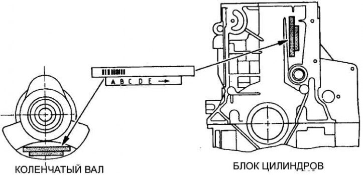
The marks on the cylinder block are on the left side of the block, and the marks on the crankshaft are on the end of the crankshaft web.
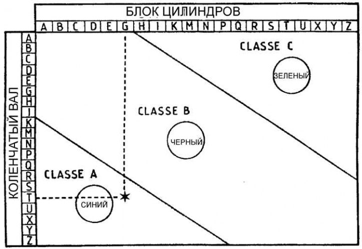
Insert Selection Chart
On early engines, the upper and lower bearings were the same thickness and only two bearing sizes were available: a standard size for use with a standard crankshaft and an oversized bearing set for installation on a reground crankshaft.
However, since February 1992, the operating clearance of the bearing has been significantly reduced, and in order to fulfill this condition, three different bushings are used, which are indicated by a colored mark on the end. The color of the label indicates the thickness of the liner. The upper shell on all bearings has the same size, and the working clearance is adjusted by setting the lower shell of the required thickness.
Aluminum block
Label color | Thickness (mm) | |
Standard | Repair | |
| Blue (class A) | 1,823 | 1,973 |
| Black (class B) | 1,835 | 1,985 |
| Green (class C) | 1,848 | 1,998 |
Cast iron cylinder block
Label color | Thickness (mm) | |
Standard | Repair | |
| Blue (class A) | 1,844 | 1,994 |
| Black (class B) | 1,858 | 2,008 |
| Green (class C) | 1,869 | 2,019 |
On the latest engines, new liners can be selected using the marks on the cylinder block. In the absence of marks, liners can only be selected by measuring the working gap.
The marks are used to select the required liner thickness.
There are two lines of identification on the crankshaft and the rear of the cylinder block: a bar code used by Peugeot in production and a row of five designations. The first designation in the sequence refers to the size of the number 1 insert. Last designation in sequence (which is accompanied by an arrow) refers to the size of the number 5 liner.
1. The designation number is determined from a specific crankshaft journal and cylinder block bearing hole.
2. On the upper axis of the nomogram, the designation of the cylinder block is marked and a vertical line is drawn through this point.
3. On the left vertical axis of the nomogram, mark the designation of the crankshaft and draw a horizontal line through this point.
4. The point of intersection of the lines indicates the size of the bushing to provide the required clearance. For example, the nomogram shows that the cylinder block points to G and the crankshaft points to T, then the intersection point within the red area determines that the cyan (class A) – most suitable for obtaining the required clearance (see fig. Insert Selection Chart).