



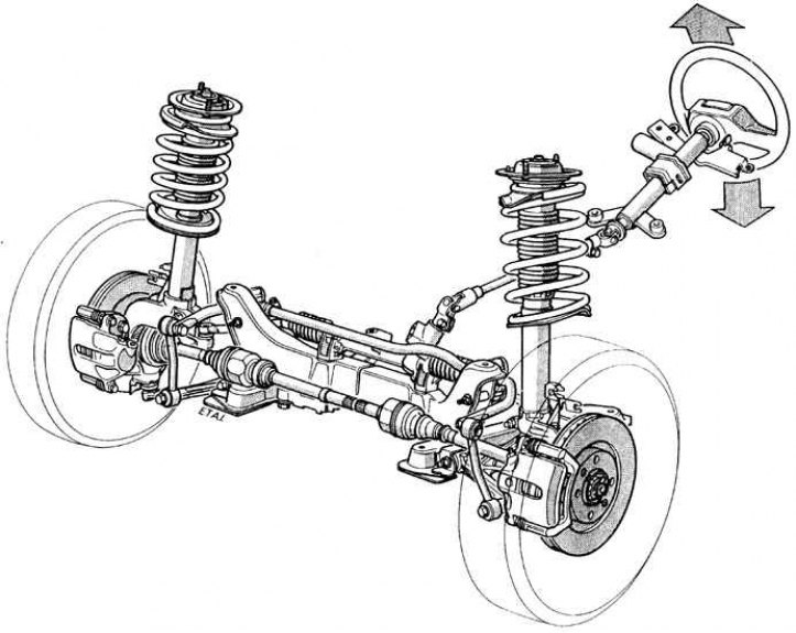
View of the front suspension with drive shafts and steering system
Drive shafts
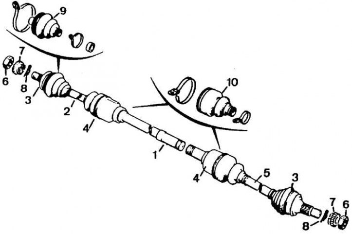
1 – connecting shaft of the right drive shaft, 2 – right drive shaft, 3 – outer joints, 4 – inner joints, 5 – left drive shaft, 6 – hub nuts, 7 – element protecting the nut from loosening, 8 – cotter pin, 9 – outer cover, 10 – inner cover
Torque from the engine is transmitted to the front wheels via two steel drive shafts of different lengths.
The outer ends of the drive shafts are inserted into the wheel hub and secured with nuts. The inner ends of the drive shafts are installed and secured in the differential.
Constant velocity joints (CV joints) are installed on both sides of the drive shafts and provide smooth and efficient transmission of torque when the suspension is operating and the front wheels are turning. The outer CV joint consists of a housing, a separator, an inner race and balls. Grooves are made in the joint housing and the race to accommodate the balls. The longitudinal grooves are made along the radius, which provides a large angle of rotation of the outer joint. The inner joint differs from the outer joint in that rollers fixed to the drive shaft are used instead of balls.
On the right side, due to the long length of the drive shaft, the inner joint is located approximately halfway along the shaft, and the intermediate support bearing is secured to the powertrain mount.
[You can find the original on the page www.PeugeotBook.ru]