



Each drive shaft consists of an inner and outer constant velocity joint (CV joint) and the shaft itself. The drive shaft can be identified by the A marks engraved on the shaft or by special stickers (see illustration 11.0).
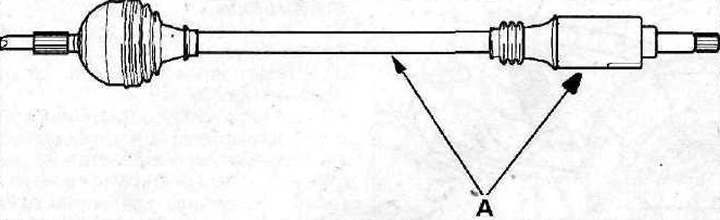
11.0 Drive shaft
A - identification notches
The splined part of the outer joint is inserted into the wheel hub and secured with a hub nut, and the inner one is attached to the gearbox. CV joints are lubricated with consistent grease, which is only filled when disassembling the joint.
The condition of the CV joint boots should be checked periodically, since if they are damaged, the grease leaks out and dirt gets into the CV joint itself, causing damage.
The drive shafts of the vehicles discussed in this manual are equipped with CV joints of two types - either "Tripod" (see illustration 11.0a), or ball bearing joints (see illustration 11.0b).
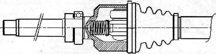
11.0 a Joint of equal angular velocities of the "Tripod" type
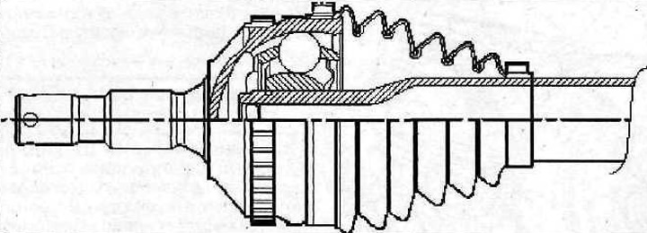
11.0b Constant velocity ball bearing joint
Removal
1. Jack up the front of the car, place it on jack stands, remove the corresponding front wheel and unscrew the hub nut, having first removed the protective cap from it.
2. Drain the transmission oil.
3. Loosen the nuts 2 of the bolts securing the right drive shaft support bearing as much as possible. There is no need to remove the heat shield 1 (see illustration).
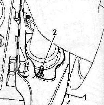
11.3 Loosen nuts 2 of the bolts securing the support bearing of the right drive shaft a as much as possible. There is no need to remove heat-deflecting shield 1. Tightening torque of nuts is 10 Nm
4. Turn the support bearing mounting bolts a quarter turn to move their heads away from the outer edge of the support.
5. Mark the position of the bolts securing the lower part of the shock absorber to the steering knuckle and unscrew them. To prevent the steering knuckle from lowering, tie it with wire to the subframe.
6. Turn the front wheels all the way to the right if the left drive shaft is disconnected, and to the left if the right drive shaft is disconnected.
7. Disconnect the tie rod end from the steering knuckle.
8. Move the steering knuckle aside and remove the drive shaft from the front wheel hub. If necessary, tap the shaft with a rubber mallet.
9. Disconnect the shaft from the gearbox, being careful not to damage the seal.
10. Remove the drive shaft seals by drilling two holes in the seal, screwing two self-tapping screws 1 into them and removing the seal using tool "a" 0336-C (see illustration).
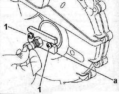
11.10 Drill two holes in the oil seal, screw in two self-tapping screws 1 and remove the oil seal using tool "a" 0336-C. Cars with automatic transmission