



Table of contents: External hinge 🠇 Inner hinge 🠇
External hinge
Plastic rings located on the outside of the protective cover
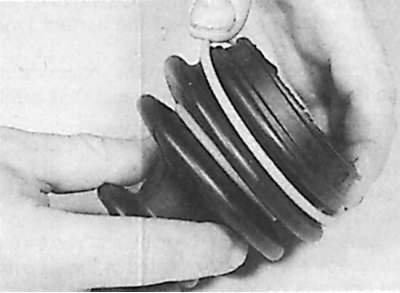
Removal
1. Remove the drive shaft.
Models with 1.4 liter engine
2. Remove the inner joint from the drive shaft.
3. Secure the drive shaft in a vice with soft jaws and remove the boot mounting clamps. Slide the protective boot down the shaft.
4. Using solvent, clean the outer joint and dry it.
5. Check the outer joint components for wear. If defects are found during the joint inspection, the entire drive shaft must be replaced.
6. Using sandpaper, clean the drive shaft from rust and sharp edges that could damage the protective boot when installing it. Slide the protective boot of the outer joint onto the shaft until the boot is installed in the groove.
7. Lubricate the working part of the outer hinge.
8. Remove the outer protrusion of the protective cover to equalize the air pressure under the cover.
9. Secure the protective cover with a large clamp.
10. Install the inner joint onto the drive shaft.
Other models
11. Secure the drive shaft in a vice with soft jaws and remove the boot mounting clamps.
12. Slide the protective cover along the shaft. Remove grease from the joint.
13. Using a hammer or soft punch, strike the joint sharply and remove the joint from the shaft.
14. Remove the retaining ring from the drive shaft groove. When installing the CV joint, a new retaining ring must be used.
15. Remove the outer hinge protective cover and, where installed, the plastic sleeve securing the inner end of the cover.
16. Using a suitable solvent, clean the CV joint and dry it. Inspect the joint.
17. Check the movement of the ball joints and the balls for damage.
18. Check the tracks along which the ball joints move on the inner and outer parts of the joint.
19. If any part of the hinge is worn, the entire hinge must be replaced. If the hinge is in satisfactory condition, a repair kit of parts must be used, consisting of a new protective cover, a retaining ring, clamps and hinge grease.
Installation
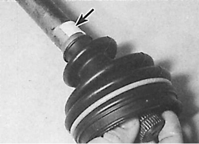
1. Slide the inner side of the protective cover onto the shaft (shown by arrow).
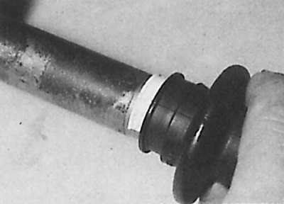
2. Install the inner end of the protective boot into the groove of the drive shaft or onto the plastic bushing (if used).
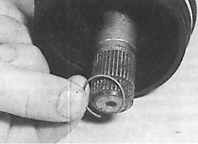
3. Install a new snap ring into the groove on the end of the drive shaft.
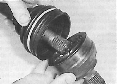
4. Align the splines of the joint and the drive shaft and install the joint on the drive shaft until it is secured with a retaining ring.
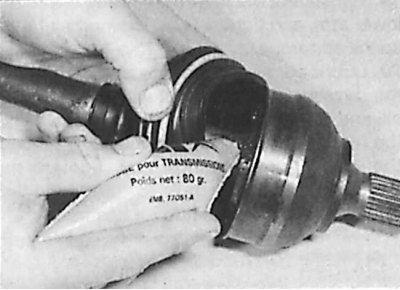
5. Fill the joint with grease and install the protective cover into the joint groove.
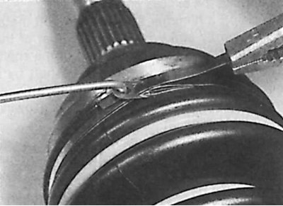
6. Secure the protective cover with clamps using a hook and pliers.
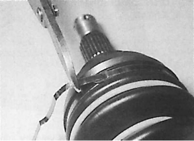
7. Bend the protruding end of the clamp and cut off the excess part.
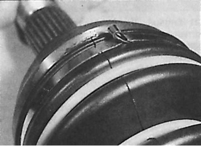
8. Fold the end of the clamp near the bracket.
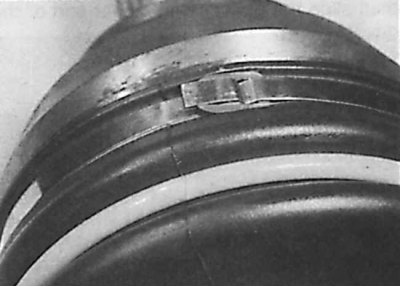
9. Press the bracket against the clamp.
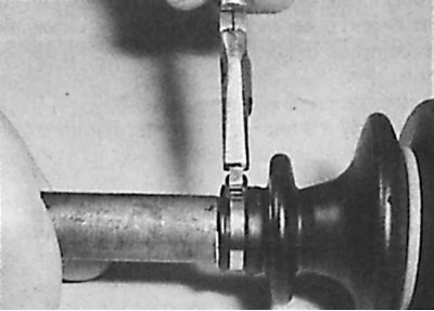
10. Lift the inner end of the protective cover to equalize the air pressure under the cover, then secure with a clamp.
11. Check the smoothness of the CV joint rotation and install the drive shaft on the vehicle.
Inner hinge
1. Remove the drive shaft from the vehicle.
Models with 1.4 liter engine
2. Secure the drive shaft in a vice with soft jaws and remove the inner joint boot mounting clamps.
3. After releasing the protective cover of the joint, pull the outer part of the joint out of the cover, remove the spring and the axial pressure head from the end of the shaft. Remove the round ring from the outside of the outer part of the joint.
4. Turn the protective cover back and remove the grease from the hinge. If the hinge rollers are not secured with retaining rings, secure them with adhesive tape.
5. Using paint or a hammer and punch, make alignment marks on the joint and drive shaft. Remove the snap ring securing the joint to the drive shaft.
6. Using a puller, remove the joint from the drive shaft. Place the puller jaws on the rear of the joint.
7. Remove the protective cover from the drive shaft by sliding it along the shaft.
8. Using a suitable solvent, clean the CV joint and dry it, without erasing the alignment marks. Inspect the joint.
9. Check the hinge parts for wear. The support rollers should rotate smoothly and evenly.
10. Cover the splines on the end of the drive shaft with tape and slide the new boot onto the drive shaft.
11. Remove the adhesive tape from the end of the drive shaft, align the marks made earlier and, using a hammer and soft drift, install the inner part of the joint onto the shaft.
12. Secure the inner part of the joint to the shaft with a snap ring, ensuring that the snap ring is correctly positioned in the groove of the drive shaft.
13. Lubricate the working part of the inner hinge. Install a protective cover on the inner part of the hinge.
14. Install the O-ring, spring and axial pressure head onto the outer portion of the inner joint.
15. Install the outer part of the inner joint and position the axial pressure head against the end of the drive shaft. Slide the outer part of the inner joint onto the shaft, compressing the spring, and position it inside the protective boot.
16. Lift the inner edge of the protective cover to equalize the air pressure under the cover with the atmospheric pressure. Secure the protective cover with a large clamp.
17. Check the smoothness of the CV joint rotation and install the drive shaft on the vehicle.
Other models
18. Remove the drive shaft.
19. Secure the drive shaft in a vice with soft jaws and remove the inner joint boot mounting clamps.
20. After releasing the protective cover of the joint, pull the outer part of the joint out of the cover and remove the spring and the axial pressure head from the end of the shaft. Remove the round ring from the outside of the outer part of the joint.
21. Turn the protective cover back and remove the grease from the hinge. If the hinge rollers are not secured with retaining rings, secure them with adhesive tape.
22. Using paint or a hammer and punch, make alignment marks on the joint and drive shaft. Remove the snap ring securing the joint to the drive shaft.
23. Using a puller, remove the joint from the drive shaft. Place the puller jaws on the rear of the joint.
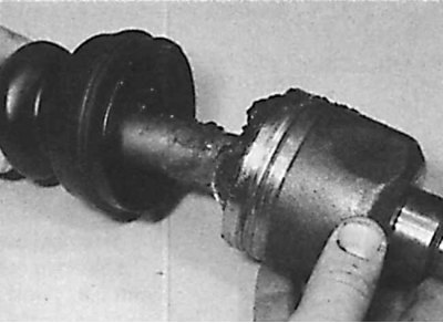
24. Wrap the splines on the end of the drive shaft with tape and remove the rubber boot and plastic sleeve from the shaft.
 |
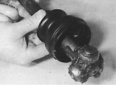 |
25. Remove the clamps securing the protective cover (drawing on the left) and remove the protective cover by sliding it along the shaft (drawing on the right).
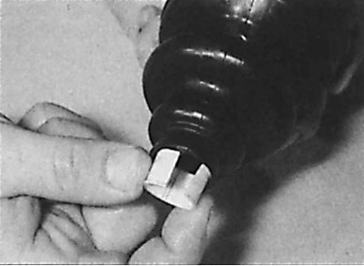
26. Remove the plastic sleeve from the cover.
27. Using a solvent, clean the hinge and dry it. Check the hinge parts for wear. The support rollers should rotate smoothly and evenly.
28. If defects are found during inspection of the inner joint, the entire drive shaft must be replaced.
29. Lubricate the working part of the inner hinge.
30. Using sandpaper, clean the drive shaft of rust and sharp edges that could damage the protective boot when installing it. Slide the protective boot of the inner joint onto the shaft, install the plastic sleeve in the recess on the shaft, and place the inner end of the protective boot on the sleeve.
31. Install the inner joint on the drive shaft and secure the protective boot in the joint grooves. Raise the inner edge of the protective boot to equalize the air pressure under the boot with the atmospheric pressure. Secure the protective boot with clamps. Install the outer joint on the drive shaft.
32. Check the smoothness of the CV joint rotation and install the drive shaft on the vehicle.