
English Русский
Български
Беларускі
Український
Српски
Hrvatski
Română
Polski
Slovenský
Magyar
Bookmark Articles Sitemap Contacts
Company Hyundai Company Opel Company Skoda Company Kia Company Mitsubishi Company LADA Company Audi
PeugeotBook.ru


Series 100   Series 200   Series 300   400-500   Series 600   Crossovers   Others
 
Peugeot 305 (1977-1989) Peugeot 306 (1993-2002) Peugeot 307 (2001-2008)

Replacement of constant velocity joints (Peugeot 307)

  • Main
  • 30X
  • Peugeot 307 (2001-2008)
  • Transmission
  • Clutch and drive shafts
  • Replacement of constant velocity joints
0
To replace the outer joint:
  • remove the axle shaft;
  • secure the axle shaft in a vice with soft jaws and remove the boot mounting clamps.
  • slide the protective cover along the axle shaft;
  • using a hammer or soft punch, strike the hinge sharply, thus displacing the hinge from the retaining ring;
  • remove the retaining ring from the axle shaft groove. When installing the CV joint, it is necessary to use a new retaining ring;
  • remove the rubber protective boot from the axle shaft;
  • using an appropriate solvent, clean the CV joint and dry it. Inspect the hinge;
  • check the movement of the ball joints and the balls for damage;
  • check the tracks on which the hinge balls move on the inner and outer parts of the hinge;
  • if any part of the hinge is worn, the entire hinge must be replaced. If the joint is in satisfactory condition, then it is necessary to use a repair kit of parts, consisting of a new protective cover, a retaining ring, clamps and joint grease;
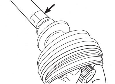
Figure 5.70. Installing the protective cover on the axle shaft

Figure 5.70. Installing the protective cover on the axle shaft

  • install the outer joint boot, wrapping the axle shaft splines with adhesive tape to protect the boot (figure 5.70);
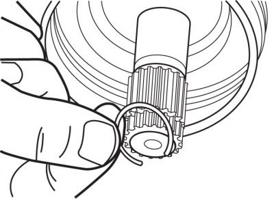
Figure 5.71. Installing a new retaining ring into the groove at the end of the axle shaft

Figure 5.71. Installing a new retaining ring into the groove at the end of the axle shaft


  • install a new retaining ring into the axle shaft groove (figure 5.71);
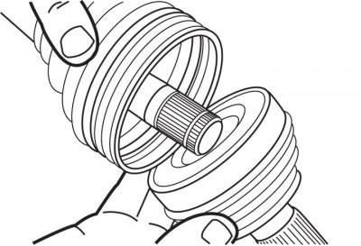

Figure 5.72. Installing the hinge on the axle shaft

Figure 5.72. Installing the hinge on the axle shaft

  • align the splines of the joint and the axle shaft and install the joint on the axle shaft until it is secured with a retaining ring by hitting it sharply with a hammer (figure 5.72);
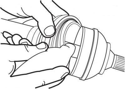
Figure 5.73. Filling the joint with grease

Figure 5.73. Filling the joint with grease

  • fill the joint with grease, turning it so that the grease gets into all the bearing races (figure 5.73). Place the remaining lubricant in the case;
  • install the cover on the hinge so that the edges of the cover fit into the grooves of the axle shaft and hinge. Secure the cover with clamps, first putting on the larger clamp and then the smaller one;
  • lift the inner end of the protective boot to equalize the air pressure under the boot, then secure with a clamp. Trim off any excess protruding part of the clamp tape;
  • check the smoothness of the CV joint rotation and install the axle shaft on the vehicle.

To replace the inner joint:


  • remove the axle shaft from the car;
  • remove the outer CV joint;
  • remove the outer joint boot, wrapping the axle shaft splines with adhesive tape to protect the boot;
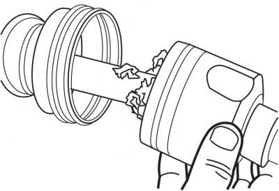
Figure 5.74. Removing the protective cover of the inner axle joint

Figure 5.74. Removing the protective cover of the inner axle joint

  • remove the clamps securing the inner hinge protective cover and slide the protective cover along the axle shaft (figure 5.74);
  • use paint or a hammer and punch to mark the position of the inner joint relative to the axle shaft. Remove the retaining ring securing the CV joint to the axle shaft;
  • using a puller, remove the CV joint from the axle shaft. Place the puller jaws on the rear of the hinge;
  • using a solvent, clean the hinge and dry it;
  • check the inner hinge components for wear. The support rollers must rotate smoothly and evenly;
  • if defects are found during inspection of the inner joint, the entire axle shaft must be replaced;
  • lubricate the working part of the inner hinge;
  • using sandpaper, clean the axle shaft from rust and sharp edges that could damage the protective cover during its installation;
  • slide the inner joint protective cover onto the axle shaft;
  • install the inner joint onto the axle shaft and secure the protective cover into the joint grooves.
  • lift the inner end of the protective cover to equalize the air pressure under the cover;
  • secure the protective cover with clamps;
  • install the outer CV joint as described above. Replace the outer hinge boot, regardless of its condition. When finished, check that both hinges move freely in all directions.
This article is available at russian, bulgarian, belarusian, ukrainian, serbian, croatian, romanian, polish, slovak, hungarian
Article reviewed by editor: Sidorov Timofey
Share information:
Previous
Peugeot 307: Clutch and drive shafts
Next

Replacing axle shafts
General information about drive shafts
Replacing the clutch disc
Replacing the hydraulic clutch drive
General information about the clutch
Replacing the intermediate bearing of the right axle shaft
See similar information for other Peugeot models

➨ Replacement of constant velocity joint boots Peugeot 405 (1987-1997)
➨ Rubber boots for axle shaft joints (GKN axle shaft) — replacement Peugeot Partner I (1996-2008)
Link to this article in different formats
Comments and feedback from visitors
No comments yet


Add two numbers 17 + 32


Peugeot 307 (2001-2008) 
  • User manual
  • Keys, doors and alarm
  • Controls and instruments
  • Driving and operation
  • Maintenance
  • Power unit
  • Petrol engines TU3 and TU5
  • Petrol engines EW10
  • Diesel engines DV10
  • Diesel engines DW10
  • Transmission
  • Clutch and drive shafts
  • Mechanical gearbox
  • Automatic gearbox
  • Chassis, running gear
  • Front suspension
  • Rear suspension
  • Steering
  • Brake system
  • Body and interior
  • Exterior (external elements)
  • Interior (internal elements)
  • Doors, locks and windows
  • Heating and air conditioning
  • Electrical equipment
  • Equipment and devices
  • Power devices
  • Airbags
  • Electrical circuits
Peugeot 306 (1993-2002) 
  • General information
  • Introduction to manual
  • Specifications
  • Gasoline engine
  • Engine repair
  • Lubrication system
  • Cooling system
  • Fuel injection
  • Ignition system
  • Diesel engine
  • Engine repair
  • Lubrication system
  • Cooling system
  • Fuel injection
  • Transmission
  • Clutch
  • Gearbox
  • Drive shafts
  • Chassis, running gear
  • Steering system
  • Front suspension
  • Rear suspension
  • Brake system
  • Electrical equipment
  • Power devices
  • Electrical circuits
Peugeot 305 (1977-1989) 
  • General information
  • Maintenance
  • Power unit
  • Gasoline engines
  • Diesel engines
  • Cooling system (gasoline)
  • Cooling system (diesel)
  • Fuel system (gasoline)
  • Fuel system (diesel)
  • Ignition system
  • Transmission
  • Clutch
  • Mechanical gearbox BB8
  • Mechanical gearbox BE1
  • Automatic gearbox ZF4
  • Shafts, hubs and wheels
  • Chassis, running gear
  • Brake system
  • Car suspension
  • Steering
  • Body and interior
  • Exterior (external elements)
  • Interior (internal elements)
  • Electrical equipment
  • Equipment and devices
  • Headlights and lighting
  • Power devices
  • Electrical circuits
  • Wiring diagrams (diesel)
PeugeotBook.ru © 2018–2026 | Mobile version | Sitemap: EN BG BY UA RS HR RO PL SK HU | Write message | Site search | Add to bookmarks | Peugeot owners
106 (1991-2003) | 206 (1998-2012) | 207 (2006-2014) | 305 (1977-1989) | 306 (1993-2002) | 307 (2001-2008) | 405 (1987-1997) | 406 (1995-2004) | 605 (1989-2000) | Partner-I (1996-2008) | Eurovans-807 (2002-2014) | Eurovans-806 (1994-2002) | J5 (1981-1993) |
Cookies are used to ensure the correct display of pages on the site.