



- with the vehicle on the ground, apply the parking brake and loosen the front wheel mounting bolts;
- raise the car on a lift;
- remove the front wheels;
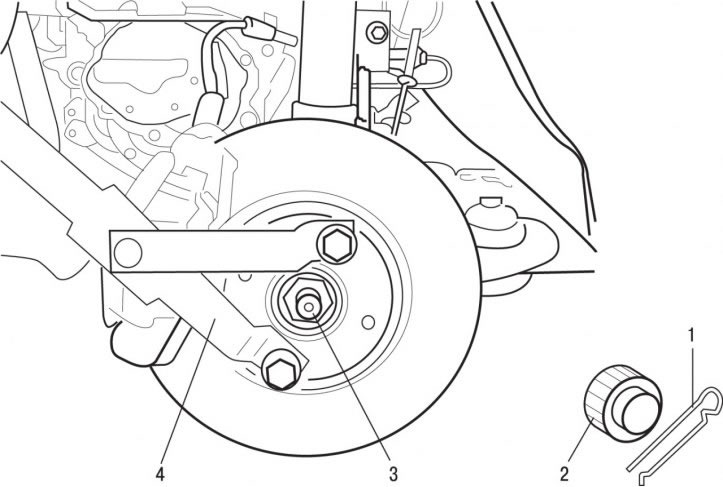
Figure 6.7. Fastening the device that prevents the hub from turning: 1 - cotter pin; 2 - cap; 3 - nut, 325 Nm; 4 - a device that fixes the hub from turning
- remove cotter pin 1 (see Figure 6.7) and remove the cap 2 that secures the axle shaft nut to the hub from loosening;
- using tool 4, secure the hub from turning and loosen and then unscrew nut 3 securing the axle shaft to the front wheel hub;
Caution! Do not use the brake to prevent the hub from turning while unscrewing nut 3—this may result in the brake disc mounting bolts being sheared off.
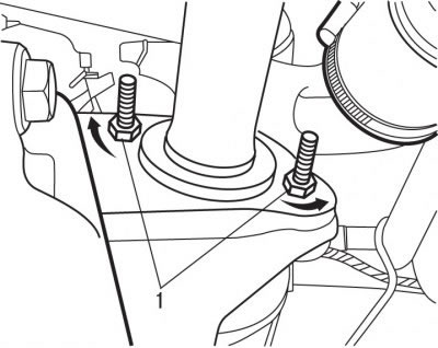
Figure 5.66. Location of nuts (1) for fastening the intermediate support of the right axle shaft
(Text taken from the website: PeugeotBook)
- unscrew the nuts as much as possible, but do not remove them (figure 5.66) fastenings of the intermediate support of the right half-axle;
- turn the bolts 90° so that their heads are offset from the outer end of the bearing;
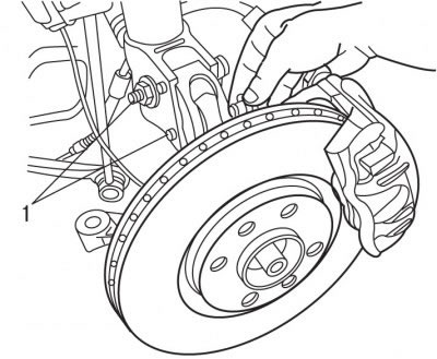
Figure 5.67. Location of bolts (1) securing the lower part of the shock absorber strut to the steering knuckle
- mark the position of the bolts that secure the lower part of the shock absorber to the steering knuckle. While holding the bolts from turning with one key, use the second key to unscrew the nuts 1 (figure 5.67). To prevent the steering knuckle from lowering, secure it to the subframe with soft wire. Remove the bolts securing the lower part of the shock absorber to the steering knuckle;
- when removing the right axle shaft, turn the front wheels to the left as far as they will go;
- when removing the left axle shaft, turn the front wheels to the right until they stop;
- unscrew the nut securing the ball joint pin of the steering knuckle to the lower wishbone. Using a ball joint puller, remove the steering knuckle ball joint pin from the lower control arm. Using a ball joint release lever, separate the lower wishbone from the steering knuckle ball joint. Be careful not to damage the constant velocity joint protective cover;
- tilt the steering knuckle to the side and remove the axle shaft from the front wheel hub;
- on vehicles with a manual transmission, drain the transmission fluid;
Caution! The AL4 automatic transmission is sealed, so there is no point in draining the oil for this operation.
- while supporting, remove the axle shaft from the gearbox without damaging the sealing ring, and remove the shaft from the vehicle. If necessary, use a rubber hammer or mallet to remove the axle shaft from the hub.
The installation of the axle shaft is carried out in the reverse order of removal, taking into account the following:
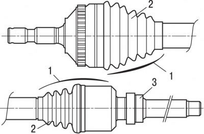
Figure 5.68. Constant velocity joints of the drive shaft: 1 - constant velocity joint; 2 - corrugated protective cover; 3 - outer bearing ring
- make sure that in the CV joints 1 (figure 5.68) there is no play;
- check the condition of the corrugated protective covers 2;
- check the freedom of rotation of the right axle shaft support bearing. If the bearing is seizing or there is noticeable axial play, it should be replaced;
- clean and lubricate the splines of the hub and axle shaft on the wheel side, as well as the splines of the planetary gears of the differential and axle shafts on the gearbox side with a universal grease;
- before installing the right axle shaft, clean and lubricate the outer ring of the support bearing 3 and its seat in the lower right engine support with multi-purpose grease;
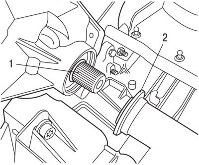
Figure 5.69. Location of the sealing ring (1) and dust ring (2) of the axle shaft
- when installing the right axle shaft, check the presence and condition of the sealing ring 1 (figure 5.69) and dust ring 2;
- check the condition of the ball joint protective boot of the steering knuckle;
- install the axle shaft into the differential, aligning the axle shaft splines with the differential planetary gear grooves;
- check that the intermediate bearing rotates easily and evenly and that there is no play between the outer ring and the inner ring;
- check that the intermediate bearing is installed correctly, then turn the bolts 90° and secure them in this position with nuts, tightening them to a torque of 10 Nm;
- using tool 4 (see Figure 6.7) secure the hub from turning and screw on and tighten the drive shaft mounting nut to the hub to a torque of 325 N·m;
- lock the nut by pressing the flange into the grooves of the splined end of the axle shaft, or secure it with a cap and cotter pin;
- install the wheels and tighten the bolts to a torque of 90 Nm;
- on vehicles with a manual transmission, add oil to the gearbox.