



- remove the air filter and the air duct connecting the air filter to the engine;
- remove the decorative engine cover;
- remove the cap from the brake fluid reservoir and use a syringe to suck out the fluid from the reservoir;
- open the bleed valve in the hydraulic system and drain the brake fluid;
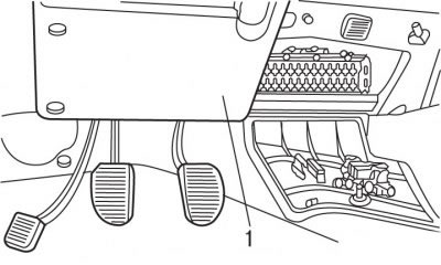
Figure 5.1. Lower left decorative panel above the pedal block (1)
- in the car's interior, remove the lower left decorative panel 1 (figure 5.1), located above the pedal block;
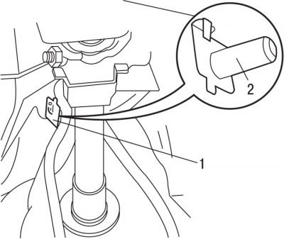
Figure 5.2. Location of the axle (1) and plastic retainer (2)
- remove axle 1 (figure 5.2), supported by a plastic retainer 2;
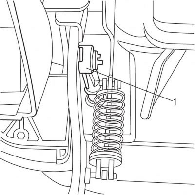
Figure 5.3. Location of the push rod (1)
- remove push rod 1 (figure 5.3);
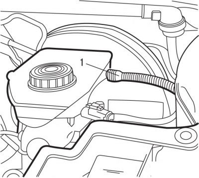
Figure 5.4. Connection point of the hose to the expansion tank with brake fluid
- disconnect hose 1 (figure 5.4) from the expansion tank with brake fluid and close it with a suitable plug;
- for vehicles with MA gearbox, do the following:
- remove the brake master cylinder and brake booster;
- for other vehicles, do the following:
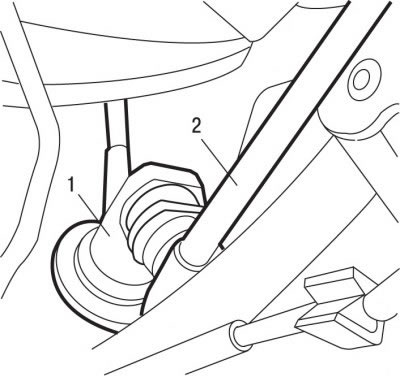
Figure 5.5. Location of the latch (1) and tube (2)
- release latch 1 (figure 5.5) and disconnect tube 2;
- turn the clutch master cylinder a quarter turn clockwise and remove it;
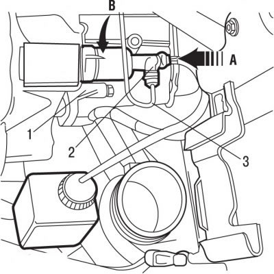
Figure 5.6. Clutch slave cylinder: 1 - clutch slave cylinder; 2 - retainer; 3 - tube; A and B are the directions of movement and rotation of the clutch slave cylinder
- without removing, release the lock 2 (figure 5.6) fastening the clutch tube to the clutch slave cylinder;
- disconnect pipe 3 from the clutch slave cylinder and move it to the side;
- disconnect the clutch slave cylinder 1 from the hydraulic circuit (by pressing in the direction of arrow A and turning counterclockwise in the direction of arrow B) and take it off.
To install the hydraulic clutch drive:
- apply a thin layer of ESSO NORVA 275 grease to the head of the push rod 1 (see Figure 5.3);
- apply a thin layer of MOLYKOTE BR2 PLUS grease to the clutch slave cylinder tip on the clutch side;
- further installation is carried out in the reverse order of removal, taking into account the following;
- remove air from the hydraulic circuits of the brake and clutch systems;
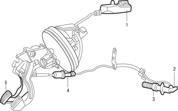
Figure 5.7. Clutch drive hydraulic circuit: 1 - filling tank; 2 - air bleed nipple; 3 - clutch slave cylinder; 4 - master cylinder of the hydraulic clutch drive; 5 - clutch pedal
- pour brake fluid into the filler tank 1 (figure 5.7) brake system to the "Max" mark;
Warning!
- 1. The brake fluid used in the hydraulic clutch drive is poisonous, so if it comes into contact with your skin, you must immediately wash the area with plenty of water. If the liquid gets into your eyes or into your body, seek medical attention immediately. Some liquids are highly flammable and can catch fire even upon contact with hot vehicle components. In addition, the fluid used in the hydraulic drive dissolves paint and plastic, so if the fluid gets on the paintwork of the car, wash it with plenty of water. Because this liquid is hygroscopic (absorbs moisture from the air), it is not recommended to use liquid that has been stored in an open container for a long time.
- 2. Any hydraulic system works properly if the air is removed from it. When removing air, add only the clean fluid recommended by the manufacturer. Never reuse fluid that has leaked from the hydraulic clutch system. If fluids of different brands have been accidentally mixed in the hydraulic system, remove the fluid and flush it with clean fluid of the required brand. If fluid constantly leaks from the hydraulic drive or air enters the hydraulic system, determine the cause and location of the leak and repair the damage. Use only approved and recommended DOT4 brake fluids. Do not use an automatic bleeding device (in this case, air bubbles may form in the liquid filling the circuit).
- rock the tank from side to side to remove air pockets. You can also press the clutch pedal about 10 times until you need to top up the brake fluid reservoir;
- add brake fluid to the brake system reservoir up to the "Max" mark;
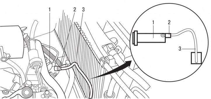
Figure 5.8. Connecting a transparent tube when bleeding air from the hydraulic clutch drive with an MA type gearbox: 1 - clutch slave cylinder; 2 - air bleed nipple; 3 - transparent tube
- connect the transparent tube to fitting 2 (figure 5.8) to remove air, lower the other end of the tube into a glass container partially filled with brake fluid and located below the working cylinder 1 of the hydraulic clutch drive. Bend the clear tube to create a siphon pointing upwards;
- remove the cap from the brake fluid expansion tank;
- press the clutch pedal sharply several times at intervals of 2-3 seconds. Unscrew the bleed nipple 2 half a turn while the pedal is pressed. While continuing to press the pedal, force the liquid in the system, along with the air, through the transparent tube into the glass container. Once the pedal reaches its extreme forward position and the fluid stops being forced out through the transparent tube, tighten the air bleed screw until it stops;
- use your hand to raise the clutch pedal to the top position;
- repeat these operations until air stops escaping from the transparent tube;
- while holding the pedal down, tighten the fitting to 7.5 Nm and remove the transparent tube;
- wipe the air bleed nipple and install the protective cap;
- add brake fluid to the brake system reservoir up to the "Max" mark;
- screw the cap onto the brake system filler tank;
- 40 times quickly before starting the engine (2 pumps per second) press and release the clutch pedal;
- check that the moment the clutch begins to engage occurs when the clutch pedal is released by 35 mm or more. Otherwise, repeat the operations to remove air from the hydraulic clutch system.
[Original is located at: peugeotbook.ru]