
Special fixture:
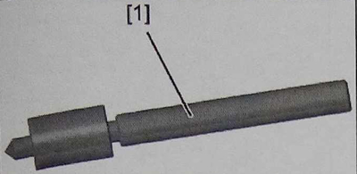
1 - centering tap 0621/3-B
Removing
Attention. Check the condition of the suspension arm after removing the rivets. In case of surface marking or paint peeling, apply anti-corrosion black paint. If significant damage occurs when removing the rivets, replace the suspension arm.
Note. It is possible to simultaneously install the right / left levers, one of which is assembled with rivets, the other with bolts / nuts.
Remove the front suspension arm (see corresponding operation).
Mark the centers of the three rivets using the tool [1].
Mount the centering gun on the head of the rivet.
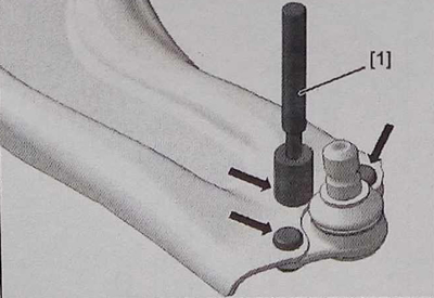
Attention. Mark the holes in the rivets on the side of the suspension arm.
Drill deep «X» from 8.0 to 10 mm rivet heads with a drill with a diameter of 3.0 to 4.0 mm.
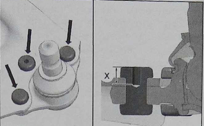
Note. Drill along the axis of the rivet.
Drill the rivet heads with a 10mm bit.
Attention. Drill the head no more than 5.0mm (size Y), so as not to damage the suspension arm (in the zone «A»).
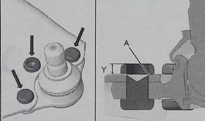
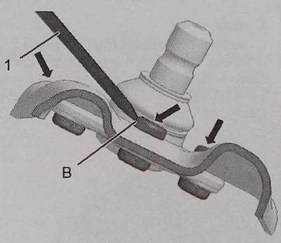
Cut off the rivet heads with a chisel (1).
Place a chisel on the head of the rivet (in the zone «b») (make sure that the chisel does not touch the suspension arm).
Remove the ball joint of the lever.
Installation
Install the ball joint from the repair kit (use the bolts/nuts supplied with the kit).
Install the bolts on the control arm side and the nuts on the ball joint side.
Tighten bolts and nuts to 55±5 Nm.
Install the front suspension arm.