



Table of contents: Removal 🠇 Installation 🠇
Attention! All Nyloc nuts that are unscrewed during removal must be replaced with new ones. The threads of these nuts are coated with an anti-loosening compound that is effective only when the nut is first used.
Caution! Do not lower the vehicle onto its wheels with one or both drive shafts disconnected from the hub, as this may damage the hub bearing. If the vehicle must be moved, temporarily insert the drive shaft into the hub and secure it with a nut.
Two different types of steering knuckle may be used, depending on the model. Earlier hub members are solid, while later ones are hollow and can be identified by the presence of a hole at the top of the unit (see picture Identification of the steering knuckle of late production). When reinstalling, note that the tightening torques differ for the two types of steering knuckles. The modified lower arms are adapted to connect with later steering knuckles, and the early lower arms and the latest steering knuckles are not interchangeable.
Front wheel hub
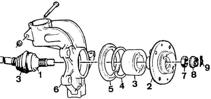
1 – drive shaft, 2 – hub, 3 – bearing, 4 – mounting expansion ring, 5 – casing, 6 – steering knuckle, 7 – nut, 8 – locking ring, 9 – cotter pin
Identifying a Late Model Steering Knuckle
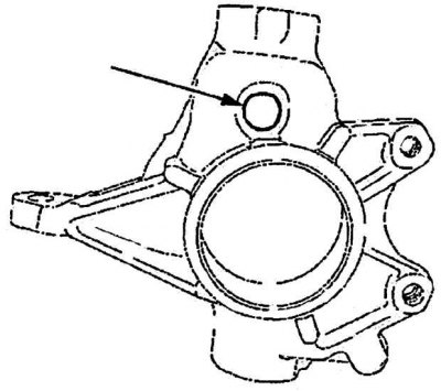
Identification of the steering knuckle of later releases is made by the hole (indicated by the arrow) at the top.
Installing the retaining cables (0903 AF) at the top of the suspension strut
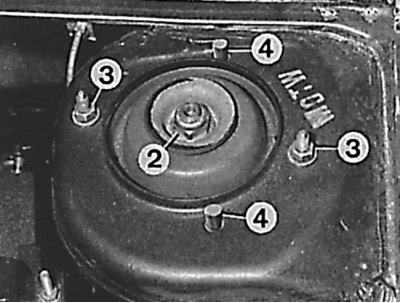
2 – shock absorber mounting nut, 3 – suspension strut mounting nuts, 4 – cable 0903 AF
Installing the retaining cables (0903 AF) at the bottom of the suspension strut

1 – lower cup of suspension strut, 4 – cable 0903 AF
Removal
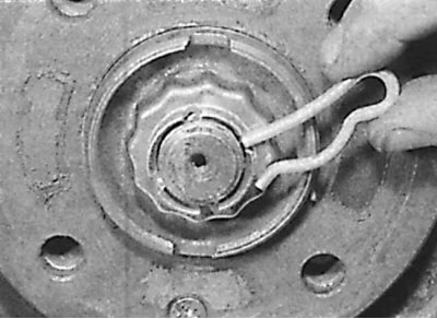
1. Remove the wheel hub cap, R-clamp and locking head. Loosen the nut securing the drive shaft to the hub with the vehicle on the ground. Also loosen the wheel mounting bolts. Raise the front of the vehicle and secure it on stands. Remove the appropriate front wheel.
2. On models equipped with ABS, remove the sensor installed on the vehicle wheel.
3. Unscrew the drive shaft mounting nut.
4. Unscrew the two bolts securing the brake caliper to the steering knuckle and remove the caliper from the brake disc. Using soft wire, tie the caliper to the suspension spring.
5. Using chalk or paint, mark the position of the brake disc in relation to the hub, then unscrew the screw securing the brake disc to the hub and remove the disc.
6. To facilitate removal of the steering knuckle from the strut, install a spring compressor and lightly compress the springs or hold the spring in a compressed state using cables (fixtures 0903 AF), for which you need to perform the following steps:
- install one of the cables in one of the two upper holes (see figure Installing the retaining cables (0903 AF) in the upper part of the suspension strut and figure Installing the retaining cables (0903 AF) in the lower part of the suspension strut);
- turn the steering wheel and install the second cable;
- insert the hooks of each cable into the holes of the lower cup;
- insert 6 mm diameter bolts into the holes to prevent the cables from falling out.
7. Remove the bolt securing the stabilizer bar connector to the lower arm.
8. Unscrew the nut securing the steering rod to the steering knuckle and remove the steering rod ball joint from the steering knuckle. To remove the steering rod ball joint from the steering knuckle, use a universal ball joint puller.
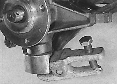
9. Unscrew the lower ball joint mounting nut and remove the ball joint pin from the lower arm.
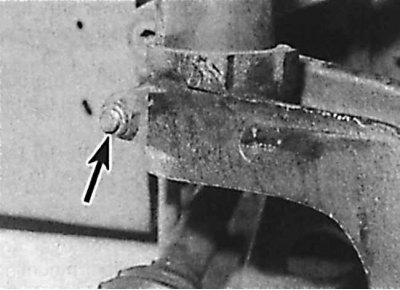
10. Unscrew the nut (indicated by arrows) and remove the steering knuckle strut clamp bolt, noting that the bolt is installed from the rear of the vehicle. A new clamp bolt and nut must be used during installation.
11. Insert the lever into the groove in the steering knuckle and widen the groove enough to remove the steering knuckle from the strut. If you have the 8.0903 AE tool, install it into the groove in the steering knuckle and turn it 90° to widen the groove enough to remove the steering knuckle from the strut.
12. Remove the steering knuckle from the end of the strut, then remove it from the end of the drive shaft and remove it from the vehicle. Using soft wire, tie the drive shaft to the vehicle body.
Installation
Installing the steering knuckle
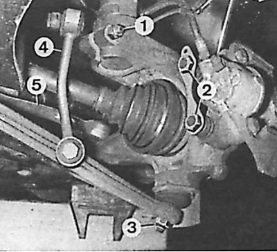
1 – bolt securing the steering knuckle to the suspension strut, 2 – caliper mounting bolts, 3 – lower ball joint nut, 4 – stabilizer link connector, 5 – steering link
Gap on later clamp protrusions
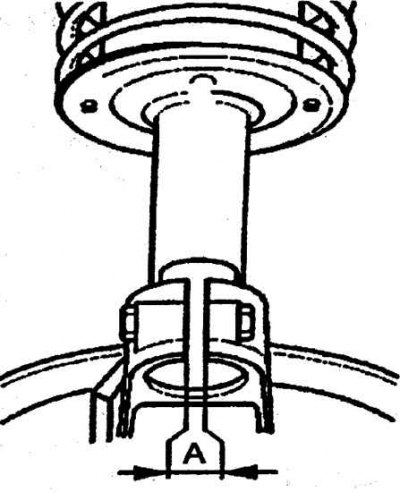
The clearance (A) at the later lugs of the steering knuckle clamp must not be less than 6.5 mm.
1. Check that the splines on the outer end of the drive shaft and the grooves in the hub are clean. Slide the hub onto the grooves in the drive shaft.
2. Slide the steering knuckle onto the bottom of the strut, aligning the gap in the steering knuckle with the tab on the end of the strut. Insert the new clamp bolt from the rear of the vehicle, thread the nut onto the bolt and tighten to the specified torque.
3. Two types of steering knuckles can be used. To install later steering knuckles, it is necessary to measure the clearance between the knuckle clamp tabs after tightening the clamp bolt (see picture Clearance on later clamp protrusions). The gap should not be less than 6.5 mm. If the gap is less than specified, perform the following steps:
- check the condition of the lower end of the strut. If the diameter of the strut has been compressed, the shock absorber may be damaged and the strut will need to be replaced;
- if the strut is not damaged, but the gap between the knuckle clamp projections is still less than specified, replace the knuckle.
4. Align the lower ball joint with the lower control arm and secure it using a new nut.
5. Connect the ball joint of the steering rod to the steering knuckle and secure with a new nut.
6. Install the stabilizer bar mounting bolt to the lower arm and tighten to the specified torque.
7. Install the brake disc.
8. Lubricate the inside and threads of the drive shaft mounting nut with clean engine oil and screw the nut onto the drive shaft. Tighten the drive shaft mounting nut to the specified torque. Check that the hub rotates freely, install the drive shaft nut locking head so that one of the safety pins aligns with the hole in the drive shaft and secure it with an R-shaped clamp.
Data published on the website www.PEUGEOTBOOK.ru
9. Remove the spring compressor.
10. On models equipped with ABS, install a wheel speed sensor.
11. Install the wheel and lower the vehicle.