
Note. All nuts disturbed during removal must be replaced without fail. This is due to the fact that the threads of these nuts are coated with a compound to lock the threaded connections (designed for one puff only). These nuts include the tie rod ball joint nut, the lower arm ball joint clamp bolt nut, and the steering knuckle clamp bolt nut. You should also replace the axle shaft nut. An appropriate thread locking compound will also be required for the brake caliper support bracket bolts.
Removing
Warning. Do not put the car on wheels when one or both half shafts are removed from the steering knuckles, as this may damage the bearing (-ov) wheels (wheels). If vehicle movement is unavoidable, temporarily insert the outer end of the axle shaft (-to her) into the hub (-s) and tighten the nut (-And) hubs.
1. Place wheel chocks under the rear wheels. Apply the parking brake fully. Raise the front of the vehicle and securely jack stands under it (see «Lifting and placing the car on supports»). Remove the corresponding front wheel.
2. Remove the R-clamp and remove the retaining cap from the axle shaft nut (pic. 2.2, a, b).
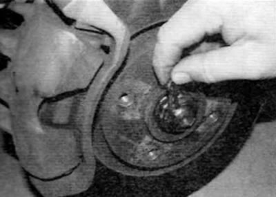
Pic. 2.2, a. Remove the R-clip...
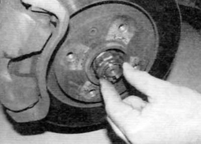
Pic. 2.2, b.... and remove the retaining cap from the axle shaft nut
3. To prevent the wheel hub from turning when the axle shaft nut is loosened, make a holding tool and use the two wheel bolts to secure the tool to the wheel hub as described in paragraph 2 of chapter 8.
4. After securing the holding tool, use a socket and extension to unscrew the axle shaft nut. If necessary, place a suitable support under the socket to prevent the socket from slipping off the nut. This nut is very tight; make sure that there is no risk of the car jumping off the supports when the nut is loosened.
5. If applicable, disconnect the steering knuckle brake pad wear sensor electrical connector. Remove the bolt securing the wiring support bracket to the top of the steering knuckle (pic. 2.5).
Pic. 2.5. Turn out a bolt of fastening of a basic arm of electroconducting to a rotary fist
6. On models with ABS, remove the wheel speed sensor from the steering knuckle as described in chapter 9.
7. If you are going to work on the hub bearings, remove the brake disc as described in chapter 9. If not, remove the two bolts securing the brake caliper support bracket to the steering knuckle and move the caliper away from the disc. Tie the caliper to the front suspension spring with wire or fishing line to avoid deforming the brake hose.
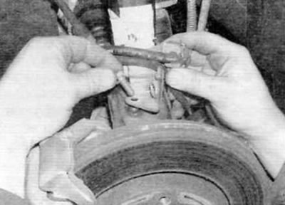
8. On all models, remove the tie rod ball joint to steering knuckle nut and use a ball joint remover to release the ball joint taper pin.
9. Loosen the nut, then remove the lower arm ball joint clamp bolt from the steering knuckle (pic. 2.9). Throw away the nuts; when installing, use new ones.
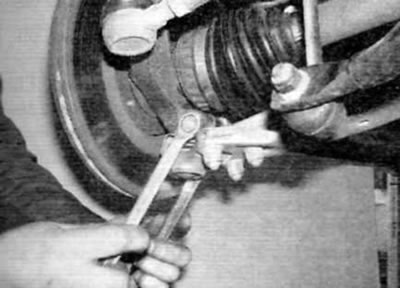
Pic. 2.9. Loosen the nut and remove the lower control arm ball joint clamp bolt from the steering knuckle
10. Drive a small chisel into the slot on the steering knuckle to widen the slot slightly to remove the ball joint pin (pic. 2.10, a). Pull the lower control arm down to release the ball joint pin from the steering knuckle. To do this, you will need to use a long rod and a wooden block, which is brought under the front subframe. Lock the rod to the suspension arm as shown. It is preferable to use a chain or, alternatively, a strong collar or cable. Press the outer edge of the rod down to release the ball joint from the steering knuckle (pic. 2.10, b).
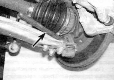
Pic. 2.10, a. With a small chisel (marked with an arrow) open the slot in the steering knuckle...
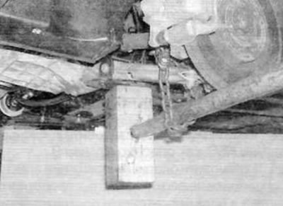
Pic. 2.10, b....then, using a chain pin or similar device, pull the lower control arm down; use a stretcher as a fulcrum
11. After releasing the ball joint, remove the protective plate that is installed on the ball joint pin (pic. 2.11).
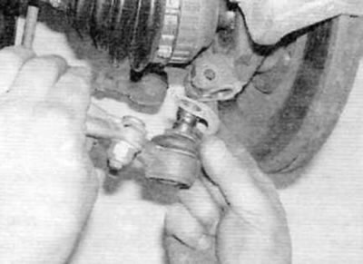
Pic. 2.11. When releasing the ball joint, remove the protective plate from the ball joint pin
12. Turn away a nut and take a clamping bolt of fastening of a rotary fist to a rack of a suspension bracket.
13. Drive a small chisel into the slot on the steering knuckle to widen the slot slightly. Pull the steering knuckle off the end of the strut, then pull it off the splined end of the constant velocity joint and remove it from the vehicle.
Installation
14. Keep in mind that all nuts disturbed during removal must be replaced without fail. This is due to the fact that the threads of these nuts are coated with a compound to lock the threaded connections (designed for one puff only). These nuts include the tie rod ball joint nut, the lower arm ball joint clamp bolt nut, and the steering knuckle clamp bolt nut.
15. Clean the splines of the outer constant velocity joint of the axle shaft and the hub, and then fully push the hub onto the splines of the axle shaft.
16. Fully push the steering knuckle onto the suspension strut, aligning the clamping slot in the knuckle with the protrusion on the strut base. Also follow that. so that the thrust lugs on the strut are in contact with the upper surface of the steering knuckle. Insert the knuckle-to-strut clamp bolt, and then screw a new nut onto the clamp bolt and tighten to the specified torque (pic. 2.16).

Pic. 2.16. Before installing the clamping bolt, align the slot in the steering knuckle with the protrusion (marked with an arrow) on the counter
17. Install the wear plate on the lower arm ball joint, and then, using the same method as when removing, insert the ball joint pin into the steering knuckle, making sure that the protrusion on the wear plate correctly enters the clamping slot. Insert the ball joint clamp bolt, and then screw on the new nut and tighten it to the specified torque.
18. Insert the tie rod ball joint pin into the steering knuckle, then screw on a new nut and tighten it to the prescribed torque.
19. If necessary, install the brake disc on the hub (for more information refer to chapter 9). Apply an appropriate thread locking compound to the caliper support bracket bolt threads. Return the caliper to its original position relative to the disc, then screw in the appropriate bolts and tighten them to the prescribed torque (see chapter 9).
20. If applicable, install the ABS wheel sensor as described in chapter 9.
21. Install the wiring support bracket to the top of the steering knuckle and securely tighten the appropriate bolt. If applicable, connect the brake pad wear sensor electrical connector.
22. Lubricate the inner surface and threads of the new axle shaft nut with clean engine oil and screw it onto the end of the axle shaft. Using the method used for removal, hold the hub from turning and tighten the axle shaft nut to the prescribed torque (see chapter 8). Make sure the hub can rotate freely.
23. Fix the lock cap on the axle shaft nut so that one of its cutouts fits into the hole in the axle shaft. Secure the cap with the R-clip.
24. Install the wheel, lower the vehicle and tighten the wheel bolts to the specified torque.