
Note. All nuts disturbed during removal must be replaced without fail. This is explained by. that the threads of these nuts are coated with a thread locking compound (designed for one puff only). These nuts include the steering gear bolt nuts.
Removing
1. Fully apply the parking brake. Raise the front of the vehicle and securely jack stands under it (see «Lifting and placing the car on supports»). Remove both front wheels.
2. Turn out a bolt of fastening of a rack of a back support of the engine/transmission to a support on a back part of the block of cylinders. Turn out a bolt of fastening of a coupler of a back support to an arm on a stretcher and remove a rack (pic. 10.2).
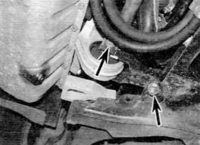
Pic. 10.2. Bolts/nuts of fastening of a coupler of a back support of the engine/gearbox (marked with arrows)
3. On models with power steering, remove the bolt (-s) pipeline fastenings (-ov) power steering to support bracket (-am) on the subframe and release the pipeline (-s) from all the clamps on the stretcher. Release the clutch cable from the brackets on the subframe.
4. If applicable, carefully remove the plastic cover and then remove the linkage crank arm pivot bolt to the subframe.
5. Turn out bolts of fastening of the steering mechanism and turn away nuts. Turn out bolts and remove remote elements from apertures in a stretcher. Secure the steering box to the exhaust downpipe using a large clamp or similar.
6. Turn out bolts of forward hinges of the lower suspension arm. Remove the nut from the respective housing if it is not secured. Do these steps on both sides.
7. Turn out two bolts of fastening of the plug of a back support of the lower arm to a stretcher. Note that the large bolt also serves to secure the anti-roll bar mount clamp (hold the nut if necessary). Remove the nut from the top of each anti-roll bar mounting clip.
8. Release the inner ends of both lower suspension arms from the subframe.
9. Place a jack with a suitable block of wood on the head under the subframe to perform a controlled lowering of the subframe.
10. Accurately measure and record the transverse and horizontal position of the subframe in relation to the chassis and underbody elements. In practice, there should be marks near the bolts on the subframe, and these can be used to set the installation position fairly accurately.
11. Remove the four rear bolts and two front bolts of the subframe, and then carefully lower the subframe from its original position and remove it from under the car (pic. 10.11, a, b). Make sure that when lowering the subframe, it does not pinch the power steering lines.
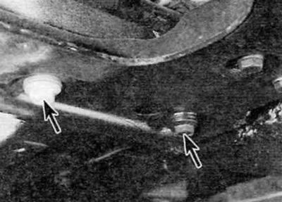
Pic. 10.11, a. Left rear bolts (marked with an arrow)...
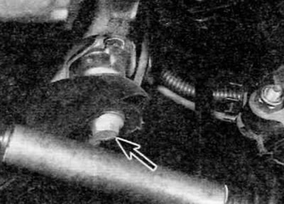
Pic. 10.11, b....and the front bolt of the front subframe (marked with an arrow)
Installation
12. Installation is carried out in the reverse order of removal, taking into account the following points:
- A) Correctly position the subframe using the measurements taken at removal or by referring to the marks made near the bolts.
- b) All nuts disturbed during removal must be replaced without fail. This is due to the fact that the threads of these nuts are coated with a compound to lock the threaded connections (designed for one puff only). These nuts include the steering gear bolt nuts.
- V) Tighten all nuts and bolts to the specified torque (if specified).
- G) Finally, check the front wheel alignment and adjust if necessary (see paragraph 24).