
English Русский
Български
Беларускі
Український
Српски
Hrvatski
Română
Polski
Slovenský
Magyar
Bookmark Articles Sitemap Contacts
Company Hyundai Company Opel Company Skoda Company Kia Company Mitsubishi Company LADA Company Audi
PeugeotBook.ru


Series 100   Series 200   Series 300   400-500   Series 600   Crossovers   Others
 
Partner I (1996-2008) Peugeot 807 (2002-2014) Peugeot 806 (1994-2002) Peugeot J5 (1981-1993)

Rear axle assembly — removal and installation (Peugeot Partner I)

  • Main
  • Пежо
  • Partner I (1996-2008)
  • Chassis, running gear
  • Car suspension
  • Rear axle assembly — removal and installation
0
Table of contents: Removal 🠇 Installation 🠇

Removal


1. Disconnect the ground cable from the battery (see "Disconnecting the battery").

2. Place wheel chocks under the front wheels. Raise the rear of the vehicle and place secure supports underneath it (see "Lifting and installing the car on supports"). Remove both rear wheels.

3. Remove the relevant exhaust system components and heat shield as described in the relevant section of Chapter 4.

4. Disconnect the parking brake cables from the equalizer plate on the parking brake lever (see chapter 9).

5. Working from underneath the vehicle, follow the entire length of each parking brake cable and release it from the clamps that secure the cables to the underbody of the vehicle. Mark the cable routing to ensure proper installation.

6. On vehicles equipped with the ABS system, disconnect the electrical connector for the ABS wheel speed sensors, which are located near the front edge of the rear axle assembly. Release the cables from the clamps on the bottom.

7. To minimize brake fluid leakage, first loosen the brake fluid reservoir cap and then tighten it again, placing a piece of plastic underneath to ensure a tight seal.

8. Wipe clean the area around the brake line connector block or rear brake pressure regulator and remove the union nuts from the two inlet brake lines (figure 15.8). Carefully disconnect the brake lines from the junction block or pressure regulator and plug the ends of the lines and open ports. Release the brake line going to the left rear brake from the clamps on the underbody.
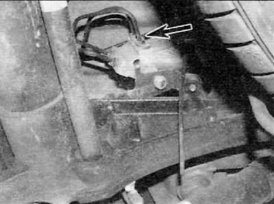


Figure 15.8. Loosen the union nuts on the two brake inlet pipes on the junction block

Figure 15.8. Loosen the union nuts on the two brake inlet pipes on the junction block


9. Make a final check to ensure all necessary components are disconnected and positioned out of the way of removal, then position the trolley jack under the center of the rear axle assembly. Raise the jack enough to support the weight of the bridge.

10. Using a long Torx bit, remove the bolts securing both rear axle supports; access to each of them is possible through an opening in the bridge side member, located directly in front of the upper shock absorber support.

11. Remove the two bolts securing each front support assembly to the underbody.

12. Lower the jack and move the axle assembly out of its standard position. Remove the bridge from under the car.

13. Inspect the rear axle mounts for signs of damage or deterioration of the rubber section and replace them if necessary. Please note that all four supports must be replaced as a set; do not replace supports one by one.

Installation


14. Installation is carried out in the reverse order of removal, taking into account the following points:
  • a) Be careful not to damage the brake lines when installing the axle under the body.
  • b) Raise the rear axle to its normal position and tighten the support mounting bolts to the specified torque.
  • c) Properly route brake lines, parking brake cables and electrical wiring (whichever is applicable) and secure with all necessary clamps.
  • d) Tighten the brake line union nuts.
  • d) Connect and adjust the parking brake cables as described in chapter 9.
  • e) Remove air from the brake hydraulic system as described in chapter 9.
This article is available at russian, bulgarian, belarusian, ukrainian, serbian, croatian, romanian, polish, slovak, hungarian
Article reviewed by editor: Nikonova Veronica
Share information:
Previous
Partner I: Car suspension
Next

Rear shock absorber — removal, inspection and installation
Rear suspension components — general information
Rear hub bearings — replacement
Rear hub assembly — removal and installation
Front subframe — removal and installation
Checking the vehicle's ground clearance
See similar information for other Peugeot models

➨ Rear brake shoe condition check — models with rear drum brakes Peugeot 106 (1991-2003)
➨ Rear axle Peugeot 207 (2006-2014)
➨ Rear axle assembly — removal and installation Peugeot 305 (1977-1989)
➨ Folding the rear seats Peugeot 405 (1987-1997)
➨ Rear Crankshaft Oil Seal (Flywheel Side) — Replacement Peugeot 605 (1989-2000)
Link to this article in different formats
Comments and feedback from visitors
No comments yet


Add two numbers 28 + 10


Partner I (1996-2008) 
  • General information
  • Introduction to the guide
  • Faults en route
  • Weekly checks
  • User manual
  • Maintenance (petrol)
  • Maintenance (diesel)
  • Power unit
  • Petrol engines
  • Diesel engines «XUD»
  • Diesel engines «DW»
  • Overhaul of petrol engines
  • Overhaul of diesel engines
  • Cooling and heating
  • Power and exhaust (petrol)
  • Power and exhaust (XUD diesels)
  • Power and exhaust (DW diesels)
  • Emission reduction
  • Starting and charging system
  • Transmission
  • Clutch
  • Mechanical gearbox
  • Drive shafts
  • Chassis, running gear
  • Brake system
  • Car suspension
  • Steering
  • Body and interior
  • Exterior (external elements)
  • Interior (internal elements)
  • Doors, locks and windows
  • Electrical equipment
  • Equipment and devices
  • Electrical circuits
Peugeot 807 (2002-2014) 
  • General information
  • Operating instructions
  • Maintenance
  • Troubleshooting
  • Power unit
  • Gasoline engines
  • Diesel engines
  • Cooling and heating
  • Fuel injection (petrol)
  • Fuel system (diesel)
  • Fuel system
  • Exhaust system
  • Ignition system
  • Transmission
  • Clutch
  • Manual gearbox
  • Automatic gearbox
  • Chassis, running gear
  • Brake system
  • Car suspension
  • Steering system
  • Body and interior
  • Exterior (external elements)
  • Interior (internal elements)
  • Electrical equipment
  • Power devices
  • Electrical circuits
Peugeot 806 (1994-2002) 
  • General information
  • User manual
  • Maintenance
  • Power unit
  • Petrol engines
  • Diesel engines
  • Lubrication system
  • Cooling system
  • Fuel injection (petrol)
  • Fuel system (diesel)
  • Ignition and exhaust systems
  • ECM Bosch Motronic MP 3.2
  • ECM Magneti-Marelli (MM)
  • Transmission
  • Clutch
  • Mechanical gearbox
  • Chassis, running gear
  • Brake system
  • Car suspension
  • Steering
  • Electrical equipment
  • Equipment and devices
  • Electrical circuits
Peugeot J5 (1981-1993) 
  • General information
  • Introduction to manual
  • Specifications
  • Gasoline engine
  • Engine repair
  • Lubrication system
  • Cooling system
  • Fuel system
  • Ignition system
  • Diesel engine
  • Engine repair (DB9)
  • Lubrication system (DB9)
  • Cooling system (DB9)
  • Fuel injection (DB9)
  • Engine repair (U25)
  • Lubrication system (U25)
  • Cooling system (U25)
  • Fuel injection (U25)
  • Transmission
  • Clutch
  • Gearbox
  • Drive shafts
  • Chassis, running gear
  • Steering system
  • Car suspension
  • Brake system
  • Electrical equipment
  • Power devices
  • Electrical circuits
PeugeotBook.ru © 2018–2026 | Mobile version | Sitemap: EN BG BY UA RS HR RO PL SK HU | Write message | Site search | Add to bookmarks | Peugeot owners
106 (1991-2003) | 206 (1998-2012) | 207 (2006-2014) | 305 (1977-1989) | 306 (1993-2002) | 307 (2001-2008) | 405 (1987-1997) | 406 (1995-2004) | 605 (1989-2000) | Partner-I (1996-2008) | Eurovans-807 (2002-2014) | Eurovans-806 (1994-2002) | J5 (1981-1993) |
Cookies are used to ensure the correct display of pages on the site.