



Table of contents: Removal 🠇 Installation 🠇
Note: Any nuts that are damaged during removal must be replaced. This is explained by the fact that the threads of these nuts are coated with a compound for locking threaded connections (designed for one puff only). These nuts include the anti-roll bar strut mounting nuts and the intermediate steering column shaft pinch bolt nut (and the tie bolt itself).
Removal
1. Fully apply the parking brake. Raise the front of the vehicle and support it securely (see "Lifting and installing the car on supports"). Place the wheels in the straight ahead position and remove both front wheels.
2. Unscrew the nut (and remove the washer) fasten the left stabilizer bar to the stabilizer and position the bar away from the stabilizer (figure 8.2). Repeat the procedure on the right side.
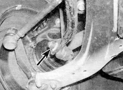
Figure 8.2. Unscrew the nut (marked with an arrow) and remove the washer securing the left stabilizer bar to the stabilizer
3. Release the clutch cable from the brackets on the subframe.
4. If applicable, loosen the power steering line support clamps at the engine and transmission.
5. From the engine compartment side, unscrew the nut securing the intermediate shaft tie bolt to the steering gear pinion, and then knock the tie bolt out of the universal joint. Discard the pinch bolt and nut; when installing, new ones should be used. Remove the metal clamp securing the intermediate shaft to the gear.
6. Mark the relative positions of the universal joint and the steering gear pinion, and then press the universal joint upward to separate it from the pinion. Lock the steering column to prevent the steering wheel from turning when the shaft is disconnected.
[View the original on the website: peugeotbook.ru]
7. Loosen the nut and remove the bolt securing the rear engine/gearbox mount clamp to the support on the rear of the cylinder block.
8. One last time, check that all relevant lines, hoses and wiring harnesses are freed and moved away from the subframe so that the rear of the subframe can be lowered.
9. Accurately measure and record the position of the subframe in the transverse direction and horizontally relative to the chassis elements and the underbody. In practice, there should be marks near the bolts on the subframe, and these can be used to set the position fairly accurately during installation.
10. Remove the four rear subframe mounting bolts. Loosen the two front subframe mounting bolts a few turns until the rear edge of the subframe can be lowered approximately 65.0 mm. To hold the subframe in this position, drive a wooden block between the rear of the subframe and the underbody of the car.
11. Loosen the two stabilizer bar clamp mounting bolts and remove the nuts from the top of the clamps. Remove both clamps from the subframe.
12. Remove the anti-roll bar from under the car and remove the support bushings from the anti-roll bar.
13. Carefully inspect the stabilizer bar components for signs of wear, damage or deterioration, paying particular attention to the support bushings. Replace worn parts if necessary.
Installation
14. Install the rubber support bushings onto the stabilizer, ensuring that the protrusions on the inside of each bushing fit into the corresponding cutouts in the stabilizer. The bushings are correctly positioned when the alignment marks on the ends of the bushings are aligned with the paint marks on the stabilizer.
15. Lift the stabilizer and move it to its standard position on the subframe. Install the support clamps, making sure their ends are correctly positioned in the hooks on the subframe, and install the bolts and nuts. Make sure the marks on the bushings are still aligned with the paint marks on the stabilizer, then tighten the support clamp mounting bolts to the specified torque.
16. The rest of the installation is carried out in the reverse order of removal, taking into account the following points:
- a) All nuts that were damaged during removal must be replaced without fail. This is explained by the fact that the threads of these nuts are coated with a compound for locking threaded connections (designed for one puff only). These nuts include the anti-roll bar strut mounting nuts and the intermediate steering column shaft pinch bolt nut (and the tie bolt itself).
- b) Correctly position the subframe using the measurements taken during removal or using the marks made near the bolts.
- c) Tighten all nuts and bolts to the specified torque (if specified).
- d) Correctly position the metal clamp on the intermediate steering shaft universal joint and ensure that the marks made during removal are aligned.
- d) Install the new intermediate shaft tie bolt and nut, ensuring that the tabs on the bolt fit into the slots in the universal joint.
- e) Finally, check the front wheel alignment angles and adjust them if necessary (see paragraph 24).