



Table of contents: Removal 🠇 Identification of lids 🠇 Removal the supports 🠇 Installation of supports 🠇 Installation 🠇
Removal
Raise and block the vehicle, raising the front wheels.
Remove the front subframe.
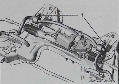
Loosen the bolts (1) and remove the assembly: anti-roll bar/supports.
Identification of lids
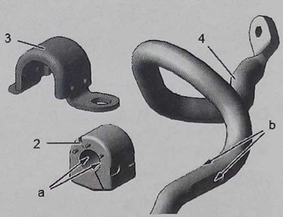
The anti-roll bar is hingedly secured by two elastic covers (2).
Correct positioning in the lateral and horizontal directions is ensured by two chamfers "a" at the bottom of the support (2) and two marks "b" on the square section (4).
The bracket (3) holds the entire assembly together.
Removal the supports
Caution: Do not allow the stabilizer bar to come into direct contact with any object or metal tool.
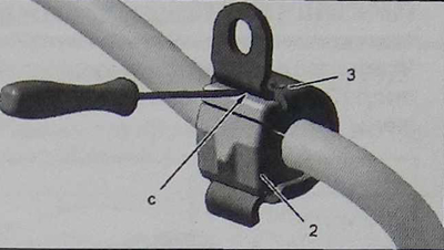
Hold the stabilizer bar on the workbench to remove the brackets (3) and supports (2).
Remove the bracket (3) using a flat-head screwdriver as a lever (in area "c").
Remove the support (2).
Installation of supports
Caution: Check the condition of the anti-roll bar (no impact marks, cracks or corrosion points). The paint covering the beam must not be damaged to the point of exposing the metal.
Move and insert the support (2).
Note: The support slot (2) must be located behind the anti-roll bar.
Align the inner chamfers "a" with the stampings "b" on the stabilizer bar beam (one on each side).
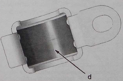
Caution. Apply sealing assembly paste for type "REMA PM600" inside the bracket (3) (in the "J" zone). Do not apply paste either to the anti-roll bar or inside the support.
Article republished from the website www.PEUGEOTBOOK.ru
Hold the support (2) to prevent any rotation.
Replace the bracket (3).
Installation
Install the anti-roll bar (4) together with its supports (2) and brackets (3).
Note: To ensure alignment of the supports (2), they must be located in zone "e".
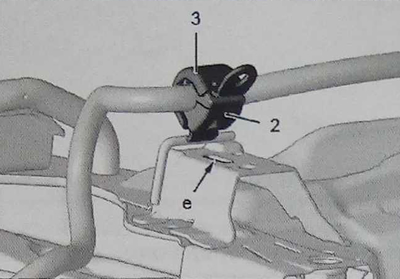
Attention. Observe the center distance of the supports: 592 mm.
Reinstall the bolts (1) and tighten to a torque of 75±7.5 Nm.
Check the position of the bracket (3) in the hooks of the subframe.
Install the engine subframe in place.