
Modulator assembly
Note. Read the warning about the danger of brake fluid given at the beginning of the operation before starting work paragraph 2.
Removing
1. Remove the battery and battery tray as described in chapter 5A. Depending on the model and operating space, remove the air filter and the remaining air intake piping for easier access to the modulator as described in the relevant part chapter 4.
2. Release the retaining clip and disconnect the electrical connector of the electronic control unit (BEU).
3. To minimize brake fluid leakage, first unscrew the brake fluid reservoir cap and then re-tighten with a piece of polyethylene underneath to ensure a tight seal.
4. Wipe clean the area around the brake line fittings on the side of the modulator and place an absorbent rag under the connections to catch any leaking fluid. Mark the location of the connections, unscrew the union nuts and carefully move the pipelines. Properly plug the ends of the lines and ports of the modulator to minimize leakage of brake fluid and prevent dirt from entering the system.
5. Turn away nuts and remove the modulator from a regular place. If there is enough space, unscrew the nut and disconnect the wire «masses» (in the presence of) from the end of the modulator return pump housing.
Installation
6. If a new modulator is installed, it comes pre-filled with brake fluid with plugs installed on the ports. Do not remove the plugs until the brake lines are connected directly.
7. Set the modulator in its original place, install the ground wire and screw on its fastening nut. Slide the modulator onto the support studs, screw on the appropriate nuts and tighten them to the specified torque.
8. Connect the brake lines to the appropriate ports as noted during removal and securely tighten the union nuts.
9. Dock the BEU electrical connector.
10. Install the battery shelf and battery (if necessary, contact chapter 5A). Install the air filter and air intake piping removed for access as described in the appropriate part chapter 4.
11. Remove the polyethylene from the reservoir of the hydraulic drive of the brakes and remove air from the entire hydraulic drive, as described in paragraph 2.
Electronic control unit
12. The electronic control unit is removed together with the modulator, as described above. BEU is an integral part of the modulator, and these elements cannot be separated from each other.
Front wheel speed sensor
Note. When installing on the sensor mounting stud, apply a compound to lock the threaded connections.
Removing
13. Disconnect the wire «masses» from battery (see «Disconnecting the battery»).
14. Fully apply the parking brake. Raise the front of the vehicle and securely jack stands under it (see «Lifting and placing the car on supports»). Remove the corresponding front wheel.
15. Release the wheel speed sensor wiring from the brackets on the suspension strut and engine compartment mudguard.
16. Track electroconducting from the gauge and disconnect an electric socket. Make a note of how the wiring is routed to ensure proper installation.
17. Loosen the nut and remove the protective cover of the wheel speed sensor (pic. 20.17).
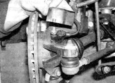
Pic. 20.17. Loosen the nut and remove the protective cover from the wheel sensor
Removing
18. Turn out a hairpin and remove the gauge from a rotary fist (pic. 20.18, a, b).
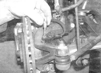
Pic. 20.18, a. Loosen the pin...
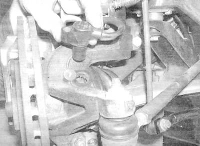
Pic. 20.18, b....and remove the front wheel sensor from the steering knuckle
Installation
19. Installation is carried out in the reverse order of removal, taking into account the following points:
- A) Before installation, clean the mating surfaces of the sensor and knuckle and apply some high temperature brake grease to the sensor mounting location in the knuckle.
- b) Clean the sensor tip surface.
- V) Apply thread locking compound to the sensor mounting stud threads and tighten the stud to the specified torque.
- G) Route the wiring as noted prior to removal.
Rear wheel speed sensor
Note. When installing, apply a compound to lock the threaded connections on the sensor mounting stud.
Removing
20. Chock the front wheels, Raise the rear of the vehicle and securely jack it up (see «Lifting and placing the car on supports»). Remove the corresponding wheel.
21. Follow the wiring from the sensor to the appropriate electrical connector, and then release the electrical connector from the appropriate clip and disconnect the electrical wiring from the main wiring harness.
22. Track the electrical wiring of the sensor and release it from the clamps. Make a note of how the wiring is routed to ensure proper installation.
23. Turn out a bolt of fastening of the gauge to the trailing arm and remove the gauge in gathering with a wire.
Installation
24. Installation is performed in sequence. withdrawal, taking into account the following points:
- A) Before installing, clean the mating surfaces of the sensor and trailing arm and apply some high temperature brake grease to the sensor mounting location in the trailing arm.
- b) Clean the sensor tip surface.
- V) Apply thread locking compound to the sensor mounting stud threads and tighten the stud to the specified torque.
- G) Route the wiring as noted prior to removal.