
Attention! All Nyloc nuts loosened during removal must be replaced with new ones. The threads of these nuts are coated with an anti-twist compound that is only effective the first time the nut is used.
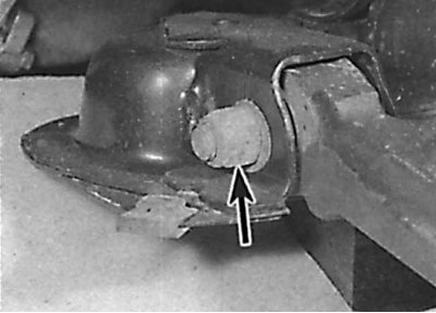
Attention! Two different types of steering knuckle can be applied, depending on the model. Earlier knuckles are solid, while later ones are hollow, and can be identified by the presence of a hole at the top of the assembly (see fig. Late production steering knuckle identification). When reinstalling, note that the tightening torques differ for the two types of steering knuckles. The modified lower arms are adapted to mate with the later knuckles, and the early lower arms and latest knuckles are not interchangeable. Withdrawal
1. Raise the front of the car and secure it on stands. Remove the corresponding front wheel.
2. Remove the bolt securing the anti-roll bar connector to the lower control arm.
3. Unscrew the nut and remove the lower ball joint from the lower arm.
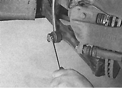
4. Secure the nut against turning and unscrew the pivot bolt (indicated by an arrow) fastening the front of the lower arm. Remove bolt.
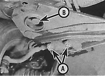
5. Loosen two nuts (A) attaching the mounting bushing of the rear of the lower arm to the lower frame (B - rear frame mounting bolt).
6. Unscrew, but not completely, the bolts securing the rear of the frame and lower the lower frame by about 10 mm.
7. Remove the lower arm.
Repair
Lever position when installing rear hub
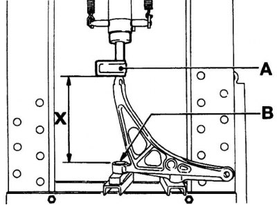
A - bushing
B - the area of application of the lubricant,
X = 254.0 mm
Alignment of marks on bushing and lever
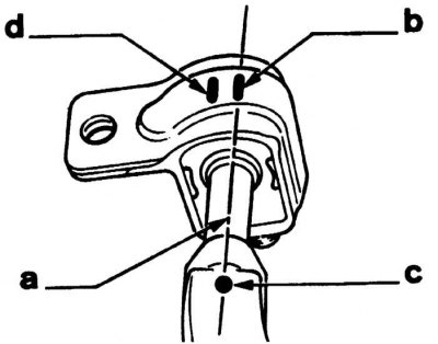
a - lubricant application area,
b, c – alignment marks,
d - unused label
1. Clean the lower arm from dirt and anti-corrosion coating. Check the lever for cracks, distortion of shape or any other defects.
2. Check pivot bolt for wear and wear.
3. Check bushings for wear and damage.
4. Worn bushings must be replaced using a press. When replacing the rear bushing, it must be installed in such a way that the marks on the bushing and the lever are aligned (see fig. The position of the lever when installing the rear sleeve and fig. Alignment of marks on bushing and lever).
Installation
Installation of the suspension arm on the cross member
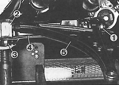
1 - front support nut, 2 - rear support, 3 - rear support mounting nut, 4 - cross member, 5 - lever
Attaching the lever to the steering knuckle
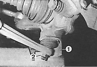
1 - casing, 2 - ball joint nut
Installation is carried out in the reverse order of removal, taking into account the following points:
- replace all Nyloc nuts;
- tighten all threaded connections to the required torque;
- check and, if necessary, adjust the wheel alignment.