
Vehicles with 2.1L XUD series engines
1. Jack up the front of the vehicle, place it on jack stands, and remove the front right wheel and fender liner.
2. Disconnect the wire terminal «masses» (-) from the negative pole of the battery.
3. Remove the water pump drive belt.
4. Remove the alternator drive belt.
5. Unscrew glow plugs.
6. Place a garage jack or a suitable block of wood under the engine to prevent damage to the sump and lift the engine to relieve its supports
7. Remove the engine mount.
8. Remove protective covers of a drive of the gas-distributing mechanism.
9. Engage fifth gear, apply parking brake.
10. Turn the crankshaft in the direction of engine rotation so that the No. 1 cylinder piston is at TDC.
11. Lock the flywheel with a suitable thrust shoe.
12. Lock camshaft gear 1 and high pressure fuel pump gear 2 (injection pump), using the M8x40 bolts and inserting them into the aligned holes on the gears and on the rear cover of the timing gear drive (see illustration).
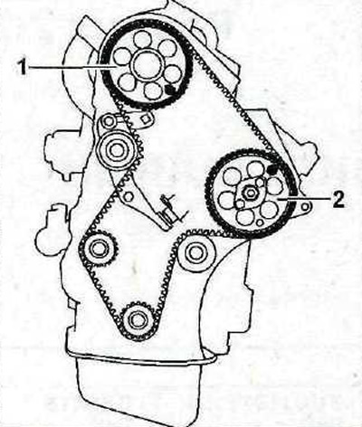
2.12 Lock the camshaft gear 1 and the injection pump gear 2 with M8x40 bolts
13. Loosen the tightening nut of the tensioner roller, carefully move the roller away from the belt, thereby loosening its tension, and remove the timing belt.
Vehicles with 2.5L DK5ATE engine
14. Remove the accessory drive belt to gain access to bolt 1 that secures the timing cover (see illustration).
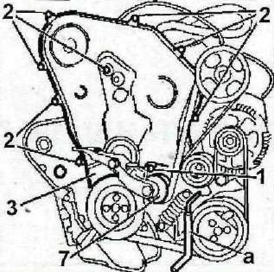
2.14 Remove the accessory drive belt to gain access to bolt 1
Attention! Depending on the location of the roller 7 (see illustration 2.14), to get access to bolt 1, the accessory drive belt can be left in place (see illustration 2.14).
15. Install thrust pin «A» 0178-Q (see illustration 2.14).
16. Unscrew bolts 1 and 2 and remove the protective cover 3 of the timing gear (see illustration 2.14).
17. Remove engine protection.
18. Stop the crankshaft by setting the stop «A» 0153-N into the corresponding hole under the exhaust manifold (see illustration).
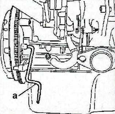
2.18 Stop the crankshaft by setting the stop «A» 0153-N into the corresponding hole under the exhaust manifold
19. Lock the camshaft gear with stop «A» 0178-A, and the injection pump gear - with an emphasis «b» 0178-B (see illustration).
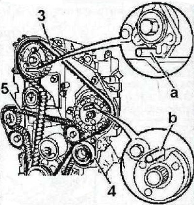
2.19 Stop the camshaft gear with a stop «A» 0178-A, and the injection pump gear - with an emphasis «b» 0178-B
20. Loosen the tension roller nut 4 and move the roller away from the toothed belt 3, thereby loosening its tension (see illustration 2.19).
21. Carefully remove the toothed belt 3 of the timing drive (see illustration 2.19).
22. Remove the tension roller 4 of the toothed belt, and then remove the belt 5 of the balancing shafts (see illustration 2.19).