
Vehicles with 2.1L XUD series engines
23. Check the condition of the toothed belt for wear and mechanical damage
24. Check the ease of rotation of the rollers, make sure that they rotate smoothly, without jamming and noise.
25. Make sure there are no signs of oil leaks on the crankshaft and camshaft seals. Replace all damaged parts with new ones.
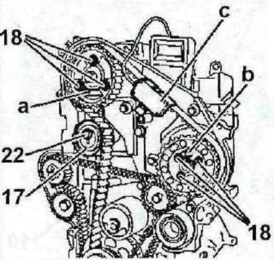
26. Lay the toothed belt, not allowing it to loosen between the gears, proceeding in the following order (see illustration):
- drive gear 1 on the crankshaft;
- guide roller 2;
- gear 3 high pressure fuel pump;
- gear 4 camshaft;
- gear 5 water pump:
- tension roller 6.
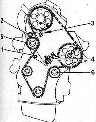
2.26 Lay the toothed belt without allowing it to loosen between the gears
27. Loosen the toothed belt tensioner bolt, turn the tensioner eccentric counterclockwise until it stops and, holding the eccentric in this position, tighten the bolt, thereby tightening the belt (see illustration).
28. Tighten the tension roller nut with a force of 10 Nm (see illustration 2.27).
29. Remove the thrust bolts that fixed the crankshaft and camshafts, as well as the stop that locked the flywheel, and turn the crankshaft two turns in the direction of engine rotation.
30. Loosen the tightening nut of the tension roller, and then tighten the nut again with a force of 10 Nm.
31. Check the correct adjustment of the gas distribution mechanism by installing thrust rollers or bolts to block the crankshaft and camshaft in the appropriate holes. If the mechanism is adjusted correctly, then the rollers will freely enter the holes and fix the crankshaft and camshafts.
32. Further, the installation of the dismantled components is carried out in the reverse order of removal.
Vehicles with 2.5L DK5ATE engine
33. Check the ease of movement of the tension roller 12 (see illustration).
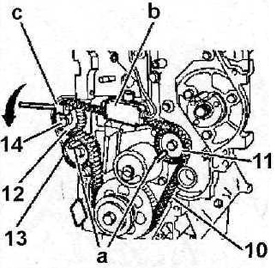
2.33 Check the ease of movement of the tension roller 12
34. Lock the balance shafts with suitable thrust rollers «A» (see illustration 2.33).
35. Lay the balance shaft belt first on the crankshaft gear, then on the balance shaft gear 11, on the tension roller 12 and gear 13 of the second balancing shaft. In this case, section 10 of the belt must be tensioned (see illustration 2.33).
36. Remove the thrust rollers «A», which stopped the balancing shafts (see illustration 2.33).
37. Fix the sensor «b» belt tension gauge (see illustration 2.33).
38. Set the lever «With» on the tension roller, turn the roller in the direction indicated by the arrow in illustration 2.33, and read the instrument readings.
The new belt should be tensioned to 70 SEEM. If the old belt is installed, then it should be tightened with a force of 51 units SEEM
39. Tighten the bolt 14 fastening the tension roller with a force of 45 Nm (see illustration 2.33).
40. Remove the gauge of the device for measurement of a tension of a belt.
41. Install the roller 15 of the tension of the toothed belt of the timing belt, tighten the bolt 16 of its fastening with a force of 45 Nm (see illustration).
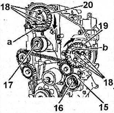
2.41 Install the pulley 15 for tensioning the toothed belt of the timing belt, tighten the bolt 16 of its fastening with a force of 45 Nm
42. Check the ease of movement of the tension rollers 15 and 17 (see illustration 2.41).
43. Lock the camshaft gear and injection pump gear with thrust rollers «A» 0178-A and «b» 0178-B (see illustration 2.41).
44. Loosen the six bolts 18 of the gears (see illustration 2.41).
45. Check the ease of movement of gear 19 of the camshaft and gear 20 of the injection pump on the hubs (see illustration 2.41).
46. Tighten by hand the bolts 18 of the gears, then loosen them by 1/6 turn (see illustration 2.41).
47. Rotate gears 19 and 20 in the direction of engine rotation (see arrows in illustration 2.41) and make sure the gear bolts are in the center of the elongated holes, and do not rest against their ends.
48. Lay the toothed belt on the crankshaft gear, then on the tension roller 15 and gear 19 of the injection pump, preventing the belt section 21 from loosening between the drive gear and the injection pump gear (see illustration).
2.48 Lay the toothed belt on the crankshaft gear a, then on the tension roller 15 and gear 19 of the injection pump
Attention! If necessary, turn the injection pump gear against the direction of engine rotation to align the belt teeth with the gear slots. It is allowed to mix the gear relative to the belt by only one tooth.
49. Similarly, place the toothed belt on the camshaft gear 20, then on the tension roller 17 (see illustration 2.48).
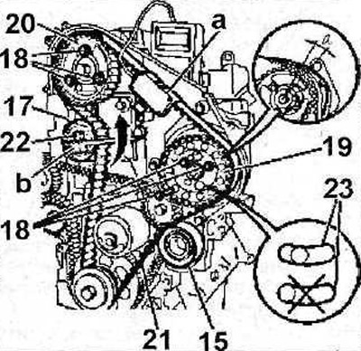
50. Attach the sensor «A» device for measuring the tension of the toothed belt of the timing drive (see illustration 2.48).
51. Turn the tension roller 17 counterclockwise with a wrench «b» 0178-E (see arrow in illustration 2.48) and read the instrument readings.
The new belt should be tensioned to 107 SEEM. If the old belt is installed, then it should be tensioned with a force of 80 SEEM units.
52. Tighten the nut 22 fastening the tension roller with a force of 45 Nm (see illustration 2.48) and remove the meter sensor.
53. Make sure that the bolts 18 for fastening the gears of the camshaft and high pressure fuel pump are located in the center of the elongated holes 23, and do not abut against their ends (see illustration 2.48). To check, you can unscrew one of the bolts. If the bolts are not centered, the toothed belt installation procedure must be repeated.
54. Tighten the gear mounting bolts first with a force of 10 Nm, and then perform the final tightening with a force of 25 Nm.
55. Remove the thrust rollers that were used to block the camshaft and injection pump gears.
56. Rotate the crankshaft 10 revolutions in the direction of engine rotation.
Attention! Turning the engine in the direction opposite to its direction is not allowed.
57. Loosen the tension of the toothed belt by turning the tension roller 17 (see illustration).
2.57 Loosen the toothed belt tension by turning the tension roller 17
58. Loosen the six bolts 18 for fastening the camshaft gears and the injection pump, then tighten the bolts by hand and again loosen them by 1/6 turn (see illustration 2.57).
59. Lock the camshaft and injection pump gears by setting suitable stops «A» And «b» into the corresponding holes (see illustration 2.57).
60. Install sensor again «WITH» toothed belt tension gauge (see illustration 2.57).
61. Turn the tension roller 17 (see illustration 2.57) counterclockwise using a special key 0178-E and read the readings of the device.
The new belt should be tensioned to 58 SEEM. If the old belt is installed, then it should be tensioned with a force of 51 SEEM units.
62. Tighten the nut 22 fastening the tension roller 17 (see illustration 2.57) with a force of 45 Nm.
63. Remove and then reinstall the sensor of the device for measuring the tension of the toothed belt.
64. Verify that the tension of the new belt is 58±3 SEEM units. If the old belt is installed, then its tension should be 51±3 SEEM units.
65. Tighten the gear bolts first to 10 Nm and then finish tightening to 25 Nm.
66. Remove all stops and special tools.
67. Adjust the tension of the balancing shaft drive belt, for which loosen the bolt 14 of the tension roller (see illustration).
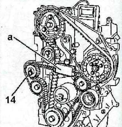
2.67 Loosen the bolt 14 fastening the tension roller
68. Install the sensor «A» belt tension gauge (see illustration 2.67).
69. Turn the tensioner with a suitable wrench and read the gauge.
The new belt should be tensioned to 31 SEEM. If the old belt is installed, then it should be tensioned with a force of 26 units SEEM
70. Tighten bolt 14 (see illustration 2.67) with a force of 45 Nm.
71. Remove and then reinstall the sensor «A» as shown in illustration 2.67, and read the instrument readings. The new belt tension should be 31±1 SEEM. If the old balance shaft drive belt is installed, then its tension should be 26±1 SEEM unit.
72. Remove all thrust rollers and stops, as well as special tools.
73. Turn the crankshaft two turns in the direction of engine rotation.
74. Install new gaskets on the protective covers of the timing gear drive.
75. Establish protective covers 4 and 6 of a drive of the gas-distributing mechanism on their seats. Make sure the seal 25 is installed as shown in the illustration.
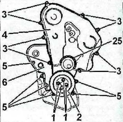
2.75 Install protective covers 4 and 6 of the gas distribution mechanism drive on their seats. Make sure the seal 25 is installed correctly
76. Tighten the bolts З and 5 securing the protective covers with a force of 10 Nm (see illustration 2.75).
77. Install the belt pulley 2 on its seat on the crankshaft and tighten the bolts 1 of its fastening with a force of 20 Nm (see illustration 2.75).
78. Install engine protection.
79. Connect and then turn the cooling hose 26 in the direction of the arrow (see illustration).
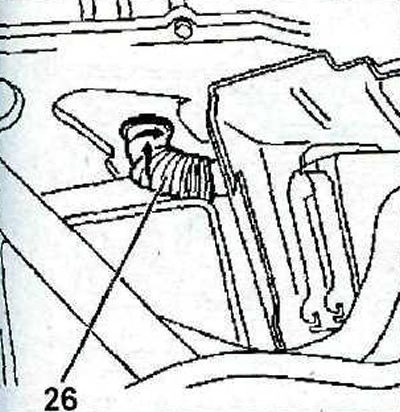
2.79 Connect and then turn the cooling hose 26 in the direction of the arrow
80. Further, the installation of the dismantled components is carried out in sequence. reverse withdrawal.