
Attention! The procedure is given on the example of vehicles with a DK5ATE engine.
1. Drain the coolant.
2. Drain gear oil.
3. Drain, if necessary, engine oil.
4. Remove the upper cross member of the front end.
5. Press the latches 1 that hold the top of the radiator (see illustration).
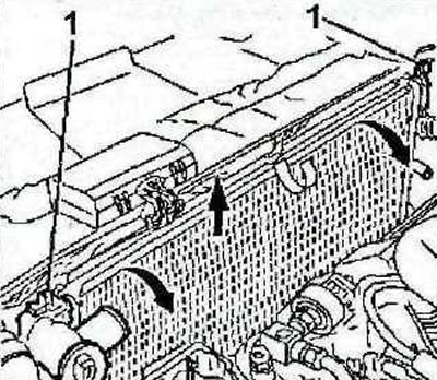
6.5 Press the latches 1
6. Disconnect the air conditioner radiator from the coolant radiator, remove the cooling system radiator (see arrows in illustration 6.5). Move the air conditioner radiator to the side without disconnecting the refrigerant circulation pipelines from it.
7. Remove the cooling radiator.
Attention! All work related to the air conditioner should be entrusted to a specialized workshop. Do not open the refrigerant circuit yourself - risk of frostbite!
8. Remove the front bumper.
9. Disconnect both drive shafts from the gearbox and secure them to the body so that they do not sag, see the relevant chapter.
10. Remove the left and right fender liner.
11. Remove the accessory drive belt, see the relevant chapter.
12. Clamp hose 2 with a suitable clamp, e.g «A» 1512 (see illustration).
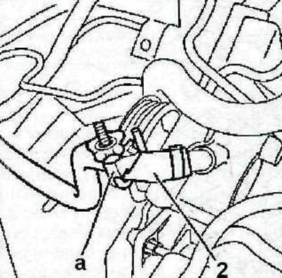
6.12 Clamp the hose 2 with a suitable clamp, e.g «A» 1512
13. Disconnect the brake hose.
14. Plug the wheel cylinder inlet.
15. Remove the battery and its tray.
16. Move away from the place of work the pump 3 of the power steering (see illustration).
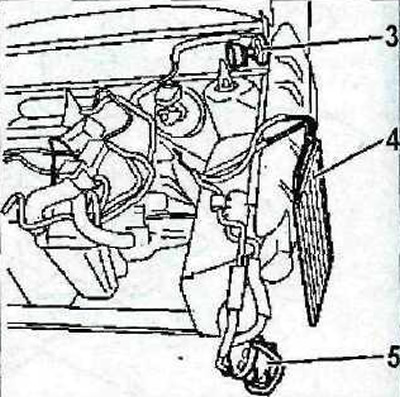
6.16 Move away from the place of work the pump 3 of the power steering
17. Cars with air conditioning (engine serial number starting from 91000000). Move the condenser 4 and compressor 5 of the air conditioner away from the place of work (see illustration 6.16).
18. Remove the engine control unit.
19. Remove the clutch slave cylinder 5 (see arrows in illustration).
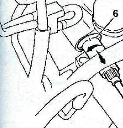
6.19 Remove clutch slave cylinder 6 (see arrows)
20. Attach the protective cap «A» (see arrows in illustration) to avoid damage to the slave cylinder 6 of the clutch.
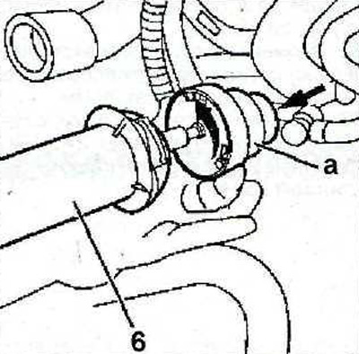
6.20 Attach the protective cap «A» (see arrows) to avoid damage to the clutch slave cylinder 6
21. Install a support beam on the limber to raise the engine and unload the power block supports, or lift the power block with a crane or hoist (see illustration).
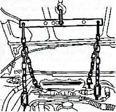
6.21 Lift the power block with a crane
22. Remove the upper support 7, and then the lower support 8 of the engine mount (see illustration).
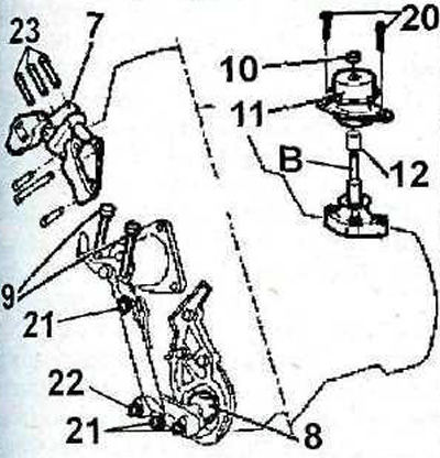
6.22 Remove the upper support 7 and then the lower support 8 of the engine mount.
Tightening torques:
- central bolt 13 of the support - 50 Nm. The bolt is tightened with a socket head bolt 20 - 20 Nm.
- nut 10 - 65 Nm;
- bolts 9-50 Nm;
- bolts 21 - 110 Nm;
- bolts 22 -60 Nm;
- bolts 23 - 70 Nm
23. Unscrew bolts 9 (see illustration 6.22).
24. Unscrew the central fastening nut 10 and remove the support 11, remove the sleeve 12 (see illustration 6.22).
25. Unscrew the central bolt 13 of the support using a socket «A» 0317-AB (see illustration).
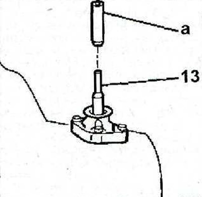
6.25 Unscrew the central bolt 13 of the support using a socket «A»
26. Remove the head 14 of the gear lever and the top trim 15 of the rear of the center console (see illustration).
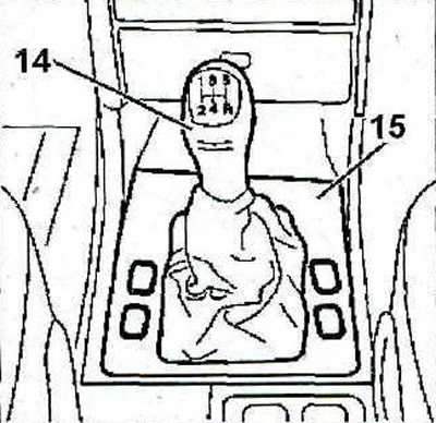
6.26 Remove the head 14 of the gear lever and the top trim 15 of the rear of the center console
27. Unscrew nuts 16 (see illustration).
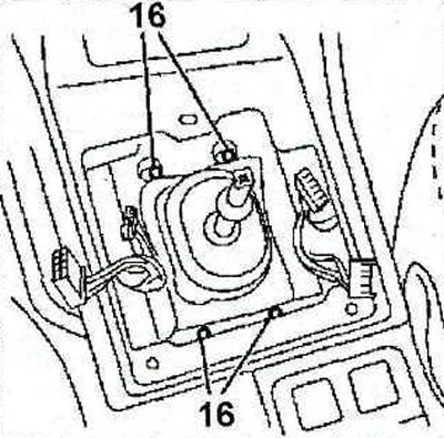
6.27 Unscrew nuts 16
28. Remove downpipe 17 (see illustration).
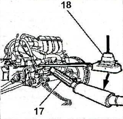
6.28 Remove downpipe 17
29. Release the body 18 of the gear lever from the fasteners (see illustration 6.28).
30. Disconnect all wires, hoses and pipelines attached to the power block housing.
31. Carefully remove the power block (see illustration).
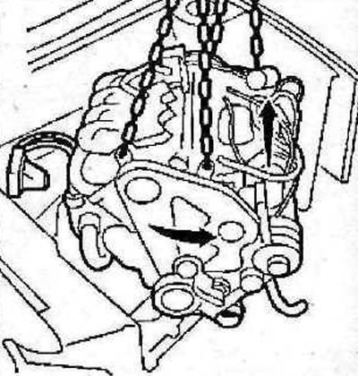
6.31 Carefully remove the power unit
The power unit is installed in the reverse order of removal.
32. The tightening torque of the power steering pump mounting bolts is 20 Nm.
33. The torque of the wheel hub nut is 345 Nm, the wheel bolts are tightened to 85 Nm.