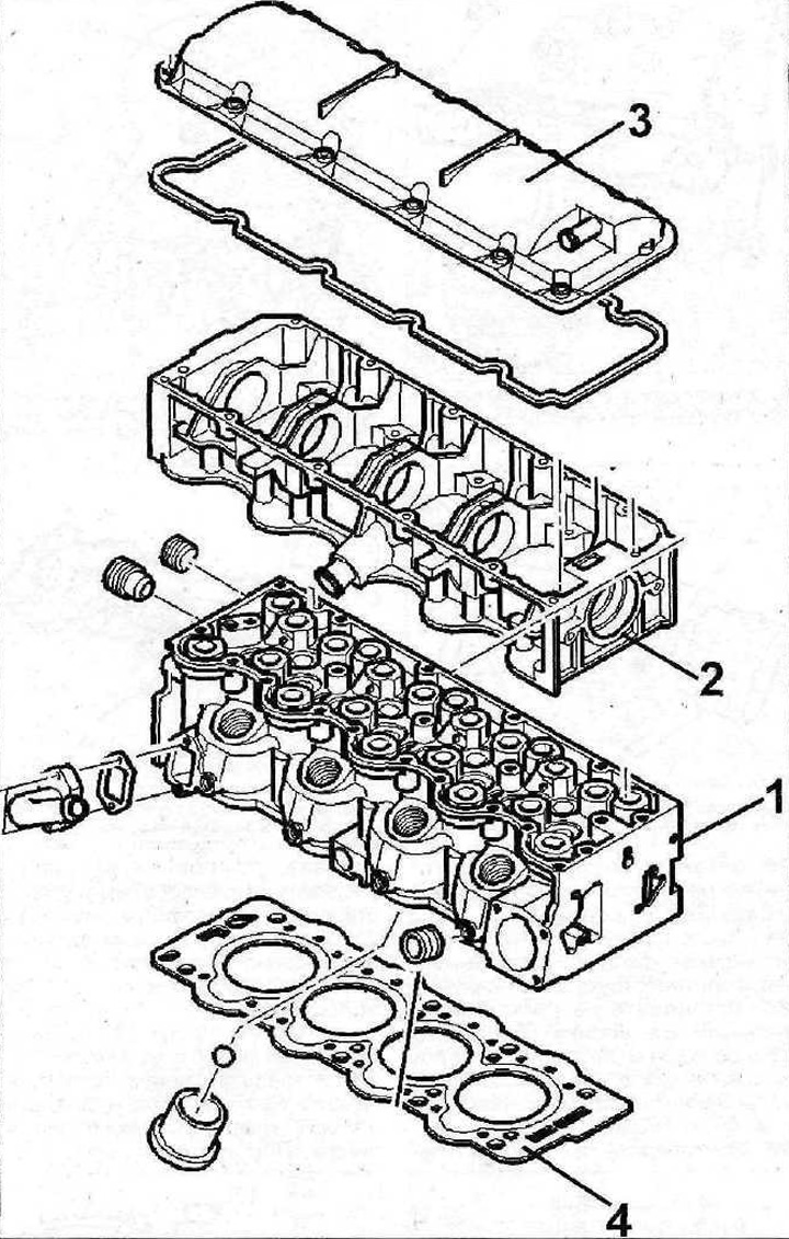
5.0 Cylinder head. Cars with engine XUD11ATE
1 - cylinder head
2 - housing of bearings of distributor shaft
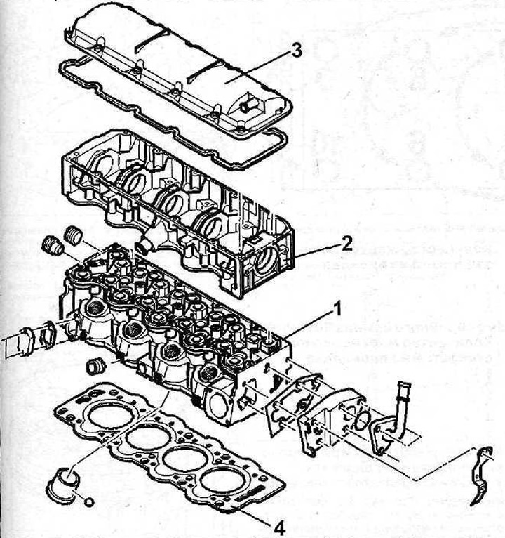
5.0a Cylinder head. Cars with engine XUD11BTE
1 - cylinder head
2 - camshaft bearing housing
3 - cylinder head cover
4 - cylinder head cover gasket
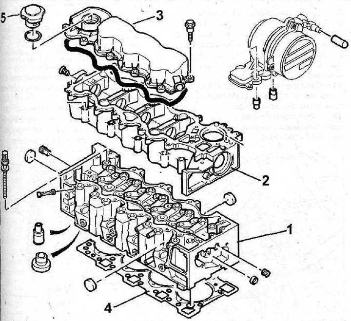
5.0b Cylinder head. Cars with DK5ATE engine
1 - cylinder head
2 - camshaft bearing housing
3 - cylinder head cover
4 - cylinder head cover gasket
5 - filler cap
Remove the cylinder head when the engine is cool. The cylinder head is usually removed to replace the sealing gasket. A defective cylinder head gasket can be identified by one or more of the following signs:
Information posted on the website: peugeotbook.ru
- a) loss of engine power;
- b) coolant leak. White exhaust clouds when engine is warm;
- c) oil leak;
- d) coolant gets into the engine oil. This causes the oil level to increase rather than decrease. Gray color of engine oil, foam on the oil level indicator (dipstick), liquid oil;
- d) engine oil getting into the coolant;
- e) the coolant is bubbling violently;
- g) poor compression in two cylinders located next to each other.
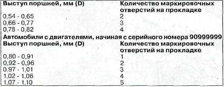
The cylinder head gasket has up to 5 holes depending on the thickness. The thickness of the gasket, in turn, depends on the size of the piston protrusion. On cars with 2.1 liter engines, in particular XUD11BTE and XUD11ATE, starting with serial number 90999999, gaskets with 5 marking holes instead of 3 are installed (see illustration).
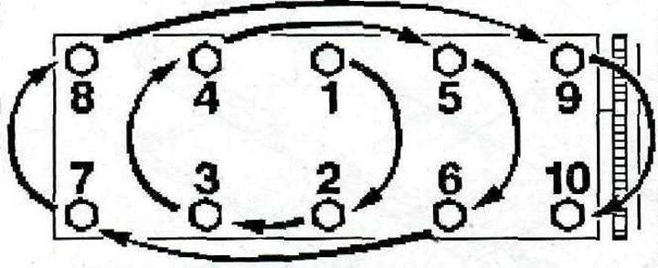
5.0v Cylinder head bolt tightening sequence
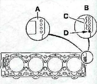
5.0g Cylinder Head Gasket
A - sealing gasket installed on engines of earlier years of production, with 2-4 holes depending on the thickness
H - sealing gasket installed on engines starting with serial number 90999999
C - holes (1-5) indicating the thickness of the gasket.
D - this hole is present on all gaskets, regardless of their thickness
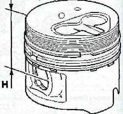
5.0d Piston
H - 44.8 mm. Pistons of this size are installed on engines of earlier years of production
H - 44.95 mm. Pistons of this size are supplied to engines starting with serial number 90999999
To measure piston protrusion, follow these steps:
1. Install the pointer type indicator on support 1 as shown in the illustration.
2. Reset the indicator by setting its arrow to 0.
3. Turn the engine crankshaft and measure the protrusion D of the corresponding piston when it is at TDC (see illustration 5.1). Repeat this procedure for each piston.
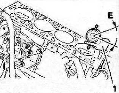
5.1 Install the pointer type indicator on support 1
4. Add the results together and divide by four to get the average piston protrusion value.
5. Select the cylinder head gasket of the required thickness depending on the value of the D value (see table).