
The outer and inner shells of the corrugated CV joints are made of different materials. The component parts of the drive shafts are shown in illustration 7.0.
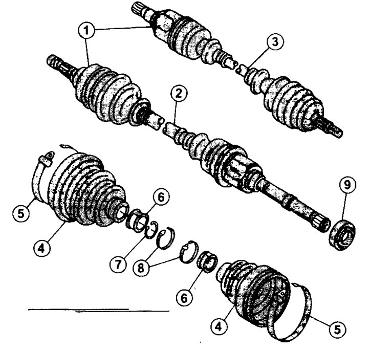
7.0 Components of both drive shafts
1 - external constant velocity joints
2 - right drive shaft
3 - left drive shaft
4 - protective covers of the outer and inner CV joints
5 - collar fastening the cover on a large diameter
6 - sleeve sleeve
7 - retaining ring
8 - collar fastening the cover on a small diameter
9 - thrust bearing
The parts of the constant velocity joint are run in to each other and cannot be replaced by installing them on other CV joints.
After removing the protective cover, all parts inside the cover must be cleaned of grease. The use of solvents for this purpose is not allowed.
The thrust bearing, if installed, can be replaced with a new one. However, to remove the old bearing, you need a puller long enough to remove the bearing from the shaft. Therefore, we recommend that this work be entrusted to a workshop if the need arises to replace the bearing
34. Clamp the removed drive shaft in a vise by placing soft tin pads on the vise jaws.
35. Remove the clamps that secure the protective covers of the CV joints.
36. Unbend the tucked-in seat belt of the hinge cup with needle-nose pliers. Be careful not to damage the surface of the shaft against which the cup rests. Knock the cup off the inner hinge.
37. Remove grease with a clean rag.
38. Mark the position of the SHRUS coupling on the shaft with paint in order to put it in its previous position during assembly.
39. Remove the slotted cage, cage support cup, spring, and retaining ring holding the pivot sleeve (see illustration).
7.39 Disassembly of the inner CV joint.
1 - position marks of the joint coupling on the shaft
2 - separator with cylindrical grooves
3 - separator support cup
4 - spring
5 - retaining ring
6 - rollers of the hinge coupling. It is recommended to wrap them with an elastic band so that they do not fall out
The retaining ring must be replaced with a new one after removal.
40. Wrap rubber band around the articulated clutch rollers to keep them from falling out.
Fasten the pivot socket so that the shaft can be pressed out of the socket. When pressing out, do not allow the shaft to fall.
42. Remove the protective cover and the rubber ring of the inner hinge.
43. Remove the hinge protective cover from the shaft and the cover from the second hinge.
44. Clean all parts, check their condition and make sure they are not worn.
The assembly of the hinge is carried out in the reverse order of disassembly.
45. Lubricate the o-ring and install it.
In order to fix the cup on the hinge separator, it is necessary to bend the edge of the seating band of the cup along the entire diameter of the contact with the shaft surface. Use a wooden punch for this.
46. Remove any escaping grease.
47. Install the swivel coupling on the shaft, being careful not to skew. The marks made before removing the coupling must match.
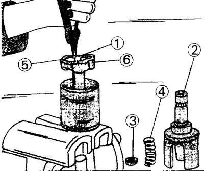
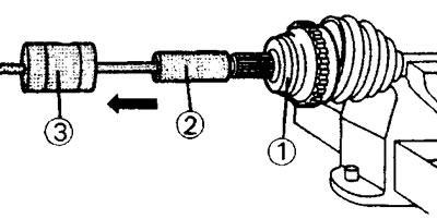
49. Stuff the hinge coupling onto the shaft, placing on its end head of the appropriate diameter and a piece of pipe (see illustration).
7.49 Stuff the hinge coupling 2 onto the shaft, placing on its end head 1 of the appropriate diameter and a pipe section
50. Secure the joint to the shaft with a circlip (see illustration). The rounded side of the thrust ring must face the coupling.
7.50 Fix the swivel sleeve on the shaft with a circlip
51. Stuff the hinge with the grease included in the repair kit, and put on the protective cover along with the fastening collar along the large diameter of the cover.
52. Bleed the air by pulling the seat band of the protective boot away from the shaft, or by inserting a screwdriver between the boot and the shaft. In this case, care must be taken so that the screwdriver does not slip off and damage the hinge.
53. Install the protective cover on the outer hinge, after filling the hinge with lubricant and remove the air from the cover.
54. Remove any grease that has come out so that road dust does not accumulate on the driveshaft parts, and the protective covers last longer.
Vehicles with ABS
Note! To replace the boot, made of thermoplastic and installed on the outer CV joint, it is not necessary to remove the boot from the inner joint. To perform the work, you will need a hammer puller and an adapter with the appropriate thread for screwing the puller onto the shaft for subsequent removal of the hinge. If there are no such devices, then the dismantled drive shaft can be brought to the workshop to replace the cover or covers of both CV joints.
55. Remove both collars of fastening of a protective cover on the external hinge and fix a power shaft in a vise.
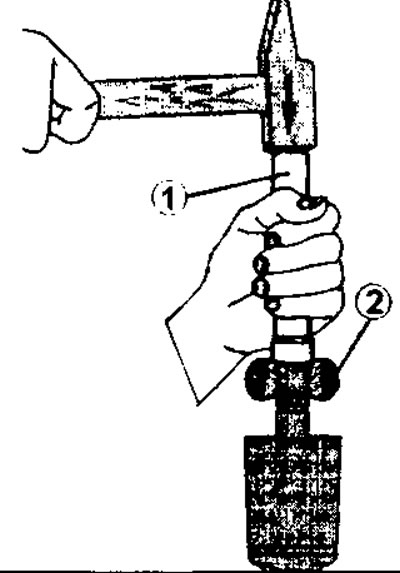
56. Remove the protective cover as shown in the illustration. The same illustration shows how to remove the outer joint from the shaft using a hammer puller. In the absence of such a puller, the hinge can be knocked down with a rubber mallet.
7.56 Remove the protective cover, as well as the hinge itself, using a hammer puller 2 and adapter 1
57. Use a screwdriver or pliers to remove the circlip from the groove at the end of the drive shaft.
58. Remove both collars securing the protective boot to the inner joint and secure the shaft in a vise, placing it vertically with the joint facing up.
59. Remove separator, spring and separator support cup (see illustration 7.39). Wrap the joint sleeve with an elastic band so that the rollers do not fall out.
60. Install the swivel sleeve so that the shaft can be knocked out of it. Take care that the shaft does not fall when disengaging from the coupling.
61. Remove the CV joint protective cover remaining on it from the shaft. If work is being done on the right drive shaft and the support bearing needs to be replaced, the shaft can now be delivered to the repair shop.
Installing the protective cover is as follows.
62. Put on the shaft from the side of the outer hinge and leave it on the shaft.
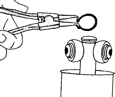
63. Install the circlip into the groove on the shaft. To facilitate the installation of the ring, you can use the hose clamp and, putting it on the retaining ring, press it into the groove (see illustration).
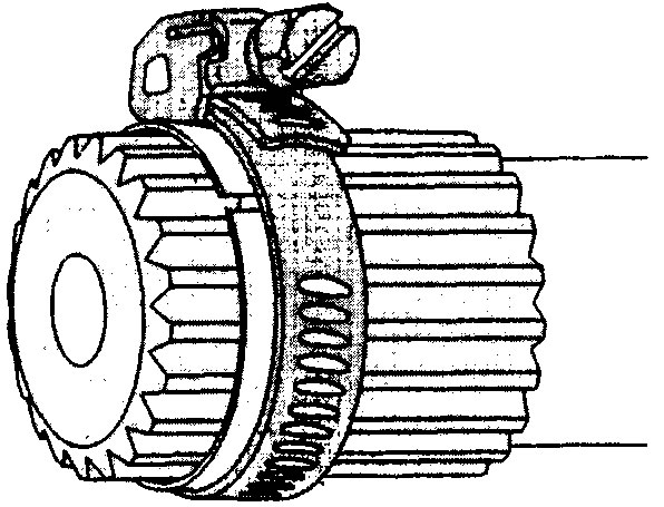
7.63 Fit the circlip into the groove on the shaft. To facilitate the installation of the ring, you can use the hose clamp and, putting it on the retaining ring, press it into the groove
64. Install the hinge housing on the shaft and stuff it with a rubber or plastic hammer. The clamp that holds the retaining ring will move and it can be removed.
65. Pack approximately 160 g of lubricant into the protective cover of the hinge.
66. Put the protective cover on the hinge and secure it with both clamps. Usually, special pliers are used to tighten the clamps.
67. Tap the joint onto the shaft with a rubber mallet and socket (see illustration 7.49) and fill the protective cover, as well as the clutch with about 160 g of grease from the repair kit.
68. Install separator base cup, separator and spring (see illustration 7.39).
69. Fix the protective cover on the CV joint. Make sure that the bulge on the boot fits well in the groove on the CV joint housing
70. Tighten the clamps of the protective cover on the SHRUS.