



A so-called three-axis "Tripod" joint is installed on the drive shaft from the gearbox side, which can move on internal V-shaped splines. The outer CV joint of the Rzep-pa is rigid, non-shiftable and depends on the engine type. The drive shaft (hub) mounting nut is tightened to a specified torque and then turned an additional 60°. Once tightened, the nut is secured with a slotted lock washer and cotter pin. Due to the significant tightening torque, special care must be taken when loosening the hub nut. If the car is placed on jack stands.
Removal
Since the oil seals that seal the holes into which the drive shaft ends are inserted will need to be replaced with new ones before installing the shafts, a suitable mandrel will be required to press in the oil seals. When installing the shaft end into the seal, use the protective guides that are sometimes included with the seals.
When removing the drive shaft, other parts will also become disconnected. Therefore, you should prepare in advance a new hub nut, a new nut for the ball joint pin of the tie rod end, which connects the tie rod to the wishbone, as well as a new nut for the tie bolt that attaches the shock absorber strut to the steering knuckle.
1. Apply the parking brake and engage first gear.
2. Loosen the wheel nuts without raising the vehicle.
3. Loosen the hub nut using a suitable socket head, after removing the slotted lock washer and cotter pin from the hub nut. You don't have to unscrew the hub nut yet (see illustration).
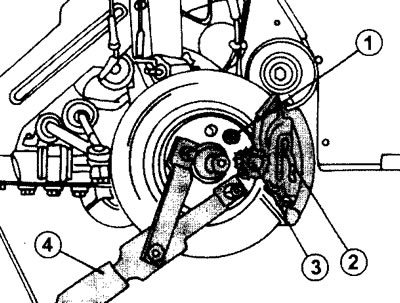
7.3 Loosen the hub nut
1- Nut
2- Cotter pin
3- Slotted lock washer
4- Stop
4. Raise the vehicle and place it on jack stands. The wheel does not need to be removed from the hub. If the hub nut is unscrewed on a vehicle already mounted on jack stands, the hub must be held from turning with an appropriate stop (see illustration 7.3). The stop handle should be on the floor.
5. Remove the drain plug on the gearbox and drain approximately one liter of transmission oil into a suitable clean container. The oil from the gearbox can be drained completely. Subsequently, the oil will not leak out through the holes where the drive shaft ends are inserted.
If the vehicle is equipped with ABS, disconnect the ABS sensor mounted on the steering knuckle to avoid damaging it during the process of removing the shafts.
6. Loosen the nuts of the tie bolts that secure the shock absorber strut to the steering knuckle and remove the bolts. To do this, press the steering knuckle down to release the strut (see illustration). Before removing the bolts, mark which side the bolts are inserted from. Before unscrewing the tie rod nuts and disconnecting the strut, make sure the vehicle is securely supported on jack stands.
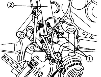
7.6 Fastening the shock absorber strut to the steering knuckle
1 - nuts of the tie bolts securing the shock absorber strut to the steering knuckle
2 - shock absorber strut
Caution! When disconnecting the shock absorber strut from the steering knuckle, be careful not to damage the protective corrugated CV joint boot. It is recommended to wrap the CV joint boot with a thick cloth.
7. Push the steering knuckle outward and the drive shaft inward, thus removing the drive shaft end from the hub. It is possible that the fit of the shaft end in the hub will be quite tight and a hammer will be needed (plastic or metal), and also a punch or a soft metal roller to knock off the shank.
After removing the shaft from the hub, secure it to the body with wire so that it does not sag and damage the hole in the gearbox under its own weight.
Left drive shaft
8. Remove the inner CV joint shaft from the transmission while keeping the drive shaft centered.
Drive shaft with support bearing
9. Loosen the nuts of the support bearing mounting bolts and turn the bolt heads a quarter turn. This releases the outer ring of the support bearing (see illustration).
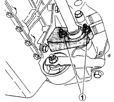
7.9 Unscrew nuts 1 of the drive shaft support bearing mounting bolts. Turn the bolts a quarter turn on the heads on the bottom of the bearing housing
10. Holding the drive shaft by the outer end, pull it until the inner end comes out of the mounting block. After releasing the drive shaft, remove the dust ring from the inner end of the shaft.
11. Remove the oil seal from the hole on the gearbox where the inner CV joint shaft is inserted. The seal can be removed with care using a screwdriver. The oil seal must be replaced with a new one even if its condition is quite good.