



1. Loosen the wheel nuts, then place the front of the vehicle on jack stands and remove the corresponding front wheel. The wheel suspension must be unloaded.
2. Loosen the tie rod end nut and press out the ball joint pin of the end from the wishbone using a puller.
3. Loosen the anti-roll bar support nut on the underside of the wishbone. Do not disconnect the stabilizer bar from the control arm yet (see illustration).
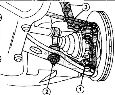
4.3 Loosen the anti-roll bar support nut on the underside of the wishbone
1 - clamping nut of the tie rod bolt on the steering knuckle
2 - stabilizer bar support nut
3 - bolts securing the steering knuckle to the shock absorber strut
5. Loosen the clamping nut of the tie rod bolt on the steering knuckle (see illustration 4.3) and push the pin with the ball head, which attaches the wishbone to the knuckle, out of the clamping slot on the steering knuckle. The ball-head pin fits into the slot quite securely, but do not try to push the slot apart by inserting a screwdriver into it. In workshops, appropriate tools are used for this purpose. If you don't have them, you can use a socket wrench of the appropriate size.
6. Insert the key into the slot and turn it as shown in the illustration. The slot width will increase and the pin with the ball head can be removed.
Article based on material from the website PeugeotBook.ru
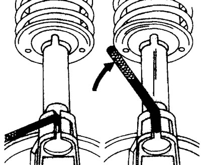
4.6 Insert a socket wrench into the slot and turn it to increase the slot width, which will allow you to remove the ball pin that secures the wishbone to the steering knuckle
7. Disconnect the shock absorber strut from the steering knuckle (see the relevant chapter).
8. Move the steering knuckle from side to side to disconnect the stabilizer link and ball joint pin. Be careful not to disengage the drive shaft from the gearbox. Secure the steering knuckle to the body with wire (see illustration).
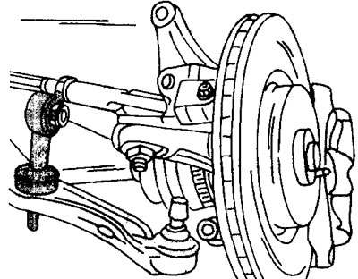
4.8 Move the steering knuckle from side to side to disconnect the stabilizer link and the ball joint pin
9. Remove bolts 1-4 (see illustration) and remove the wishbone.
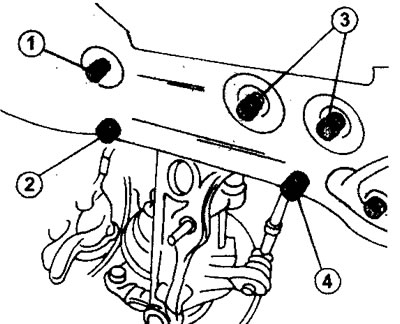
4.9 Bolts 1-4 for fastening the transverse arm. Remove the bolts and the wishbone
The wishbone cannot be repaired and, if necessary, should be replaced with a new one.
When installing the control arm, proceed in the following sequence.
10. Lubricate the control arm mounting bolts 1-4 with Loctite.
11. Install the transverse arm in place and screw in bolts 1 - 4. Bolts 3 secure the anti-roll bar struts (see illustration 4.9).
12. Secure the anti-roll bar to the strut and insert the ball-head bolt into the slot on the steering knuckle.
13. Insert the clamping bolt and tighten the nut to a torque of 70 Nm (see illustration 4.3).
14. Raise the steering knuckle and secure it to the bottom of the shock absorber strut.
15. Insert the steering knuckle and shock absorber strut mounting bolts and tighten their nuts to a torque of 110 Nm.
16. Load the suspension to approximately its normal position and tighten the wishbone mounting bolts (see illustration 4.9). Tighten bolts 1 and 2 to a torque of 110 Nm, and bolts 3 to a torque of 85 Nm. Tighten bolt 4, which secures the rear part of the steering arm, to a torque of 110 Nm.
Removing the anti-roll bar is quite difficult because it requires disconnecting the steering column drive pinion and the universal joint with the crosspiece. In addition, it will be necessary to lower the engine subframe. Since these works can only be performed with the vehicle mounted on a hydraulic lift, we do not recommend removing the stabilizer yourself. Experience shows that there is no need to replace the anti-roll bar during the entire service life of the vehicle.