



13. Lubricate the working surface of the new seal and drive the seal into the hole. The oil seal must be positioned so that its outer surface is flush with the surface of the gearbox housing. It is important to remember that the sizes of the outer and inner CV joint shaft seals differ in their diameters.
Installation of drive shafts is performed depending on the shaft.
Drive shaft without support bearing
14. Insert the protective guide, if supplied with the seals, into the shaft end hole on the gearbox (see illustration). Insert the inner CV joint shank into the same hole so that the shaft splines align with the gear teeth.
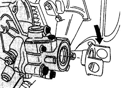
7.14 Insert the guide to protect the oil seal from damage when installing the drive shaft
15. Remove the protective guide by pulling it by the side tabs (see illustration).
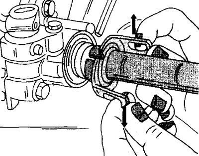
7.15 Remove the protective guide by pulling it by the side tabs
Drive shaft with support bearing
16. Check the movement of the support bearing and make sure that it does not have excessive play. Replace the bearing if necessary.
17. Replace with a new dust ring if the condition of the old one is unsatisfactory.
18. Apply a thin layer of grease to the outer ring of the support bearing and the dust ring.
19. Insert the inner end of the drive shaft through the hole of the support bearing, and then put the dust ring on it. The flat side of the dust ring should face the transmission.
20. Insert the shaft end into the hole on the gearbox. Pre-install the guide that protects the oil seal in the gearbox from damage, if any. If the outer ring of the support bearing comes out of the housing, the ring must be hammered back into place with a hammer with a soft metal striker.
21. Make sure the support bearing is positioned correctly and back off the bearing mounting bolts a quarter of a turn.
22. Tighten the nuts of the bolts to a torque of 10 Nm (see illustration 7.9).
23. Make sure the drive shaft dust ring fits tightly against the gearbox.
All types of drive shafts
24. Insert the outer end of the drive shaft into the steering knuckle and hub until it stops.
25. Feed the steering knuckle inward and connect its top to the bottom of the shock absorber strut.
26. Insert the tie bolts into the holes, observing the marks indicating which side the bolt heads should be on. Screw the nuts onto the bolts and tighten them to a torque of 110 Nm.
27. Install the ABS sensor, if equipped.
28. Thread the new nut onto the hub axle, but do not tighten it.
29. Lower the vehicle and apply the parking brake.
30. Tighten the nuts of both hubs using a socket wrench and then tighten to the required torque of 100 Nm using a torque wrench. From this position, tighten the nuts by 60° (see illustration).
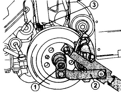
7.30 Tightening the hub nut
1 - socket head
2 - stop for holding the hub from turning
3 - bolts for fastening the steering knuckle and shock absorber strut
31. Install the slotted lock washer onto the hub nut and insert the cotter pin (see illustration 7.3). It goes without saying that the hole on the lock washer and the nut must match.
32. Tighten the wheel nuts.
33. Fill the gearbox with transmission oil or add the required amount depending on whether the oil was drained completely or partially.