
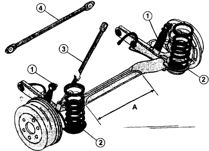
5.0 Rear axle with wheel suspension on trailing arms connected by a beam mounted on the body.
1 - shock absorber
2 - twisted spring
3 - anti-roll bar
4 - stiffening bar. The stiffening bar is installed on cars «Van», intended for the transportation of small consignments of goods
Attention! In the autumn of 1996, the coil springs of the rear suspension underwent certain changes. On cars from earlier years of production, the suspension springs have three marks applied in yellow paint. Current springs have only two yellow marks. However, new springs can be installed instead of the old ones, including in «mixed» when only one of the springs is replaced.
Removing
The procedure for removing and installing the rear axle for minivans (Evasion, etc.) and for vehicles with a body «van» (Jumpy and Scudo) slightly different. This is due to the presence of a stiffening bar in trucks, which determines the removal of the anti-roll bar. Up to the removal of the stabilizer, the procedure for all types of cars is the same.
1. Place the vehicle on jack stands so that the rear wheels are free to sag.
2. Remove rear wheels.
3. Loosen nuts 1 and 2 (see illustration) and, placing a garage jack under the bridge beam, slightly raise the beam to compress the shock absorbers a little.

5.3 Fastening the upper 1 and lower 2 supports of the rear suspension shock absorbers. To remove the shock absorbers, the rear axle must be raised using a garage jack 3
4. Unscrew nuts completely and remove shock-absorbers. Perform the specified work on both sides of the bridge.
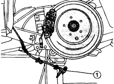
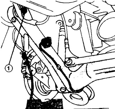
5. Disconnect the brake hose at point 1 (see illustration). To do this, unscrew the union nut, holding the hose from turning by the hexagon, and release it from the mount.
5.5 Disconnect the brake hose at point 1. To do this, unscrew the union nut, holding the hose from turning by the hexagon, and release it from the mount
6. Plug the holes in a suitable way. We recommend wrapping them with tape to keep dirt out.
7. Unscrew the jam nut and adjusting nut on the parking brake cable.
8. Disconnect the parking brake cable from the fork and from the lever on the brake mechanism. The same applies to the parking cable of the second rear brake. Release both cables from the mountings on the body.
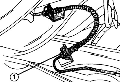
9. Remove the wheel speed sensors, if the vehicle is equipped with ABS, release the sensor wires from the suspension mount and leave the sensors hanging on the wires (see illustration).
5.9 Remove the wheel speed sensors, if the vehicle is equipped with ABS, release the sensor wires from the suspension mount and leave the sensors hanging on the wires
Minivans
10. Install a garage jack under the rear axle beam and raise the axle. The next step is to remove the anti-roll bar.
11. Unscrew the lower nut 1 fastening the rod of the brake force regulator of the brake mechanisms of the rear wheels (see illustration).
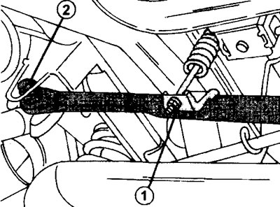
5.11 Mounting the anti-roll bar (minivans)
1 - fastening the rod of the brake force regulator of the brake mechanisms of the rear wheels. Fastened with two nuts.
2 - a bolt of fastening of the stabilizer to a body
12. Mark the mounting position of the upper regulator nut and also unscrew it (see illustration 5.11).
13. Turn away a bolt 2 fastenings of the stabilizer to a body (see illustration 5.11). If necessary, the stabilizer bar can be detached from the suspension itself.
14. Lower the rear suspension assembly onto the garage lift. When doing this, keep an eye on the coil springs and remove them as soon as they are released.
15. Place suitable wooden blocks under the hubs and lower the suspension so that the hubs stand on the wooden blocks (see illustration 5.16).
5.16 Trailing arms are attached to the body with bolts 1. These bolts should be tightened when the car is on wheels
16. Turn out bolts of fastening of the right and left trailing arms 1. The assistant at the same time should keep a suspension bracket on the elevator.
17. Remove the garage lift along with the rear suspension from under the car.
Cars with a body «Van»
18. Place a garage jack under the rear axle and raise the axle.
19. Unscrew the lower nut 1 fastening the rod of the brake force regulator of the brake mechanisms of the rear wheels. illustration).
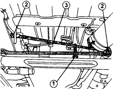
5.19 Fastening the anti-roll bar and stiffening rod.
1 - fastening the brake force regulator of the brake mechanisms of the rear wheels. Fastened with two nuts
2 - bolts for attaching the stabilizer and stiffening rods to the body
3 - stiffening bar
20. Mark the mounting position of the upper regulator nut and also unscrew it (see illustration 5.19).
21. Turn away bolts 2 fastenings of the stabilizer and bar of rigidity (see illustration 5.19). Remove the stiffener.
22. Lower the rear suspension assembly onto the garage lift. When doing this, keep an eye on the coil springs and remove them as soon as they are released. The further procedure is the same as above.
Installation
Installation of the rear axle is carried out in the reverse order of removal, subject to the following requirements.
23. Get the garage lift with the rear axle installed on it under the raised car and place the axle with the hubs on the wooden blocks (see illustration 5.15).
24. Install both trailing arms in place and insert the mounting bolts.
25. Screw the nuts onto the bolts of the trailing arms and tighten them, but not to the torque prescribed in the specifications.
26. Lubricate the wheel speed sensors. In workshops, a special lubricant is used for this. Lubricate the sensor mounting bolts with Loctite paste and fix the sensors by tightening the mounting bolts with a torque of 10 Nm. Lay and fasten the wires of both sensors as they were before removal.
27. Install the coil springs and raise the bridge so that the top and bottom ends of the springs are in place. An assistant is needed to perform this operation so that both springs can be controlled at the same time.
28. Insert a bolt 2 fastenings of the anti-roll bar (see illustration 5.11). Tighten the bolt by hand.
29. Fasten the brake force regulator rod of the brake mechanisms of the rear wheels with the nut 1 (see illustration 5.11). Install the upper nut in its original position, guided by the marks made during removal. After that, lock the lower nut relative to the upper one without changing the position of the upper nut.
30. Connect the brake hose (see illustration 5.4).
31. Fasten the parking brake cables. After installing the bridge, it will be necessary to check the adjustment of the parking brake cable. The rear wheels should not turn if the parking brake lever is tightened to the 4th or 5th tooth of the sector.
32. Install shock absorbers by attaching them to the upper and lower supports (see illustration 5.3). Do not tighten the shock absorber mounting bolts.
33. Remove air from the brake system (see relevant chapter).
34. Install the wheels and screw on the wheel nuts.
35. Lower the car. Rear suspension bolts and nuts must be torqued to specification using a real vehicle on wheels. Access to some bolts and nuts in this case is difficult. You can use a hydraulic lift with a platform, if available, or drive into the pit.
36. Torque tighten the rear suspension bolts and nuts. Do not forget that the shock absorber mounting bolts are tightened with different torques.
- the bolt of the upper shock absorber support is tightened with a torque of 90 Nm (see illustration 5.3);
- the bolt of the lower shock absorber support is tightened with a torque of 65 Nm (see illustration 5.3);
- the bolt 2 of the stabilizer bar is tightened with a torque of 60 Nm. If the stabilizer was also disconnected from the suspension, then this bolt is tightened with a torque of 80 Nm (see illustration 5.11);
- bolts 1 for fastening both trailing arms are tightened with a torque of 85 Nm (see illustration 5.15);
- the wheel bolts are tightened with a torque of 100 Nm.