
Removing
Attention! The inclined position of the suspension struts determines the angle - camber. For this reason, the upper suspension strut mounts must not be interchanged. There is a reference mark on the upper suspension strut mounts (see illustration 2.0). Looking in the direction of travel (letter C with arrow), then the upper support, indicated by the letter A in the illustration, belongs to the cool post, and the support indicated by the letter B, to the right.
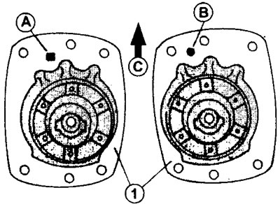
2.0 The upper suspension strut mounts must be installed in accordance with the marking. The upper support, marked with the letter A, refers to the left pillar, and the support marked with the letter B, to the right, when viewed in the direction of movement indicated by the arrow
1. Apply the parking brake and engage first gear.
2. Remove wheel nuts.
3. Loosen the hub nuts. This requires a replaceable socket head.
4. Place the front of the car on a jack so that the wheels sag freely under their own weight. Now you can remove the wheels, as well as completely unscrew the hub nut.
5. Remove the brake pads (see relevant chapter) and remove the caliper bolts. Fasten the caliper itself to the wire
6. Disconnect the wire from the ABS wheel speed sensor.
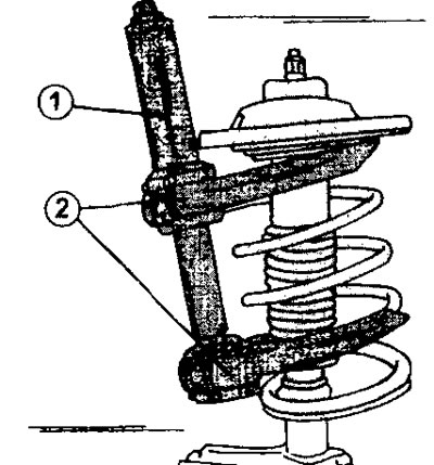
7. Turn away nuts of both bolts of connection of an amortization rack and a rotary fist and wring out a rotary fist down that the rack was released. At the same time, secure the wheel drive axle shaft so that it does not fall or become disconnected from the gearbox (see illustration).
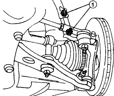
2.7 Unscrew the nuts 1 of both bolts connecting the suspension strut and the steering knuckle and press the steering knuckle down to release the rack
8. Turn out bolts of fastening of the top support of an amortization rack (see illustration). Ask an assistant to hold the stand so that it does not fall. After that, the rack must be removed by filing forward.
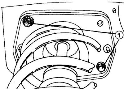
2.8 Bolts 1 of fastening of the top support of an amortization rack
Attention! The suspension strut can be removed together with the wheel wire half shaft. In this case, it is necessary to disconnect the steering knuckle from the transverse arm (see below).
Installation
The suspension strut is installed in the reverse order of removal. At the same time, we remind you once again that in order to maintain the camber, you cannot swap the upper supports of the racks.
If the suspension strut was removed together with the drive shaft, then first replace the oil seal in the hole for the axle shaft shank in the gearbox.
9. Insert the shaft shank into the hole on the gearbox and slide it fully into the gearbox.
10. Place the suspension strut in the desired mounting position and secure its upper support to the mudguard by screwing in the two mounting bolts. Tighten the bolts with a torque of 45 Nm.
If the axle shaft of the wheel drive was not removed together with the rack, then insert its shank into the steering knuckle and hub (see relevant chapter). After that, put the suspension strut in the required mounting position and secure it to the mudguard as described above.
11. Fix the lower part of an amortization rack on a rotary fist and insert both bolts of fastening.
12. Screw on the nuts and tighten them with a torque of 110 Nm.
13. Remove the support fixed by a wire on a body and connect with a rotary fist. Tighten both bolts.
14. Install the wheel and secure it with bolts.
15. Lower the car and tighten the wheel bolts to 100 Nm.
16. Tighten the hub nut.
Bulkhead
The main work that is performed on the shock absorber is the replacement of the coil spring or the upper support. If the shock absorber is damaged, then the rack should be changed completely (see illustration 2.0a).
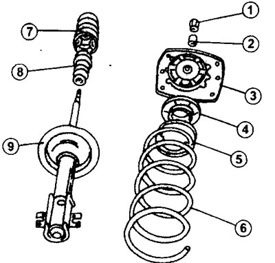
2.0a Parts of the suspension strut.
1 - a nut of fastening of a shock-absorber rod. Tightening torque 90 Nm
2 - spacer sleeve
3 - top support
4 - upper spring cup
5 - bearing
6 - shock absorber spring
7 - protective cuff
8 - compression stroke buffer
9 - shock absorber
In order to disassemble the suspension strut, it is necessary to compress the spring to release the corresponding parts of the strut from the load. Figure 2.0b shows strut spring clamps used in workshops. If there are no such clamps, then you can use clamps with cam clamps, which are identical in handling to clamps.
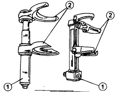
2.0b Clamps for compression of a spring of an amortization rack
17. Clamp the spring strut in a vise and install the spring remover (see illustration).
2.17 Clamp the spring strut in a vice and install tool 1 to remove the springs. In the absence of special clamps, you can use clamps with cam clamps 2
18. Compress the fully coiled shock strut spring by tightening the clamp nuts until the ends of the spring are clear of the top and bottom cups.
19. Unscrew the shock absorber rod nut located in the middle of the upper strut support using the appropriate socket head. Hold the shock absorber rod itself with a second socket wrench from turning.
20. Remove all parts above the top end of the spring.
21. Remove the spring from the shock absorber together with the retaining clamp. Be careful not to damage the shock absorber rod. After that, remove all parts on the shock absorber. The protective cuff is simply put on the shock absorber rod and can be easily removed. Under the cuff is a rubber compression stroke buffer.
22. Check the condition of all parts and replace if necessary. The height of the front end of the car above the roadway may change due to the shock strut spring, which has weakened during long-term operation of the car. When purchasing a new spring, be sure to include the vehicle identification number and year of manufacture.
The procedure for assembling the suspension strut is as follows.
23. Install the compression stroke buffer and protective collar on the shock absorber rod.
24. Secure the stand vertically in a vise.
25. Put the spring clamped in the clamp on the shock absorber rod. The lower end of the spring should fit into the seat.
26. Install all the parts under the top support of the rack, and place the top support itself so that the upper end of the spring takes its seat.
27. Fix the shock absorber rod with a new nut and tighten it with a torque of 90 Nm. The shock absorber rod must be kept from turning when tightening the nut.
28. Release the clamp that holds the spring in a compressed position. Release the spring slowly, making sure that the ends of the spring remain in their seats.
29. Loosen the vise and remove the stand.