



- raise the front of the car and secure it on stands;
- remove the front wheels;
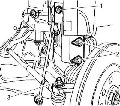
Figure 6.2. Location of shock absorber strut mounting nuts: 1 - nut for fastening to the anti-roll bar link; 2 - nut for fastening to the steering knuckle; 3 - nut for fastening the steering rod end to the ball joint
- unscrew nut 3 (see Figure 6.2) fastening the ball joint journal of the tie rod end to the steering knuckle, being careful not to damage the protective boot of the constant velocity joint of the drive shaft;
- using a puller, remove the ball joint from the steering knuckle;
- unscrew the fastening nut 1 (see Figure 6.2) and disconnect the stabilizer bar link from the shock absorber strut;
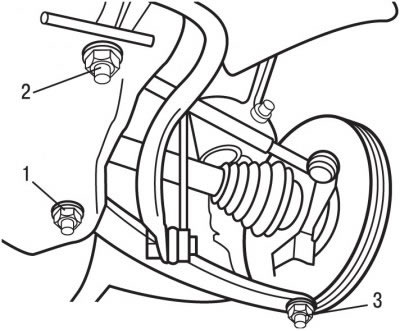
Figure 6.21. Location of fastening nuts: 1 - nut securing the front lower wishbone to the subframe; 2 - nut securing the rear lower wishbone to the subframe; 3 - ball joint of the steering knuckle
- unscrew the front 1 and rear 2 nuts (figure 6.21) lower wishbone mounts to the subframe;
- unscrew nut 3 securing the ball joint pin of the steering knuckle to the lower wishbone;
- using a ball joint puller, remove the steering knuckle ball joint pin from the lower control arm;
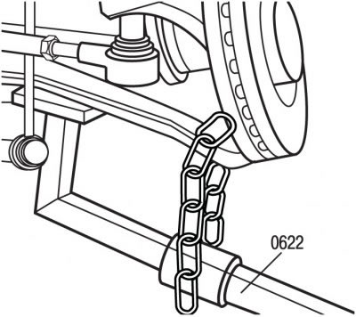
Figure 6.22. Using lever 0622 to separate the ball joints of the steering knuckle, to remove the lower wishbone from the ball joint journal of the steering knuckle
- using the 0622 lever for separating the ball joints, separate the lower wishbone from the ball joint of the steering knuckle (figure 6.22). Be careful not to damage the protective cover of the constant velocity joint of the drive shaft;
- move the shock absorber forward and remove the front mount of the lower control arm;
- remove the lower wishbone.
Install the lower control arm in the reverse order of removal, taking into account the following:
- when installing, replace with new self-locking nuts;
- tighten the nuts and bolts to the specified torques.
(You can find the original on the resource: peugeotbook.ru)