
- raise the front of the car and secure it on stands;
- remove the front wheels;
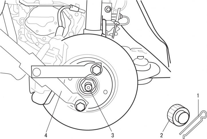
Pic. 6.7. Fastening the device that fixes the hub from turning: 1 - cotter pin; 2 - cap; 3 - nut, 325 Nm; 4 - a device that fixes the hub from turning
- remove cotter pin 1 and remove cap 2 (pic. 6.7), fixing the nut of the drive shaft to the hub from unscrewing;
- using fixture 4, fix the hub from turning and loosen and then unscrew the nut 3 securing the drive shaft to the front wheel hub;
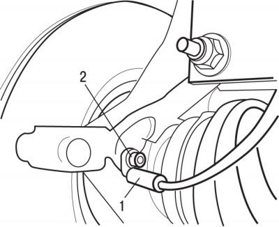
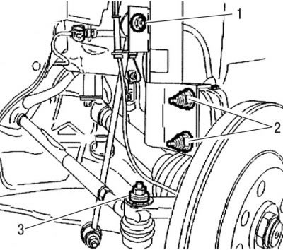
Pic. 6.8. Bolt location (2) ABS sensor mounts (1)
- unscrew bolt 2 and remove ABS sensor 1 (pic. 6.8) from the steering knuckle;
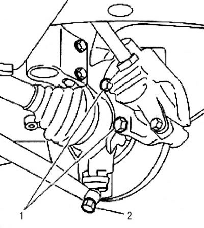
Pic. 6.9. Location of caliper bolts (1) and nuts (2) fastening the trunnion of the ball joint of the lower transverse arm to the steering knuckle
- remove bolts 1 (pic. 6.9), remove the front brake caliper and tie the caliper to the body with a soft wire. The caliper must not hang on the brake hose;
- remove the brake disc;
- unscrew the nut 2 fastening the pin of the ball joint of the steering knuckle to the lower transverse arm;
- using a ball joint remover, remove the steering knuckle ball joint pin from the lower arm;
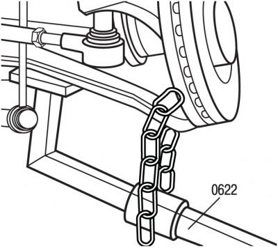
Pic. 6.22. Use of lever 0622 to disengage the steering knuckle ball joints, to remove the lower transverse link from the steering knuckle ball joint trunnion
- use the lever 0622 to separate the ball joints, separate the lower transverse link from the ball joint of the steering knuckle (pic. 6.22). At the same time, do not damage the protective cover of the constant velocity joint of the drive shaft;
Pic. 6.2. Arrangement of nuts of fastening of an amortization rack: 1 - nut fastening to the anti-roll bar; 2 - nut fastening to the steering knuckle; 3 - nut fastening to the ball joint of the tie rod end
- unscrew nut 3 (see fig. 6.2) fastening the pin of the ball joint of the tie rod end to the steering knuckle, while being careful not to damage the protective cover of the constant velocity joint of the drive shaft;
- using a puller, remove the ball joint from the steering knuckle;
- note the position of the bolts securing the lower part of the shock absorber to the steering knuckle;
- holding the bolts from turning with one wrench, unscrew the nuts with the second wrench 2 (see fig. 6.2);
- remove the bolts securing the lower part of the shock absorber to the steering knuckle;
- tilting the steering knuckle away from the car, remove the drive shaft from the front wheel hub and secure the drive shaft to the car body with soft wire;
- remove the steering knuckle from the vehicle, while being careful that the drive shaft does not come out of the differential sockets.
Attention! Under no circumstances should the vehicle be lowered onto the wheels with two or one of the drive shafts removed, as this will damage the wheel bearings. If it is necessary to install the car on wheels and move it with the shafts removed, install its external hinge instead of the drive shaft and tighten the hinge fastening bolt to 325 Nm.
Install the steering knuckle in the reverse order of removal, taking into account the following:
1) when installing, replace with new self-locking nuts and caliper mounting bolts, on the threads of which apply a locking compound that prevents them from self-unscrewing;
2) tighten the nuts and bolts to the following torques:
- a nut of fastening of a spherical support of a tip of steering draft - 50 N·m;
- suspension strut mount to the steering knuckle - 90 Nm;
- ABS wheel sensor mounting bolt - 9 Nm;
- hub nut - 325 Nm;
- caliper mounting bolts to the steering knuckle - 105 Nm;
- brake disc mounting bolt - 10 Nm.