
English Русский
Български
Беларускі
Український
Српски
Hrvatski
Română
Polski
Slovenský
Magyar
Bookmark Articles Sitemap Contacts
Company Hyundai Company Opel Company Skoda Company Kia Company Mitsubishi Company LADA Company Audi
PeugeotBook.ru


Series 100   Series 200   Series 300   400-500   Series 600   Crossovers   Others
 
Partner I (1996-2008) Peugeot 807 (2002-2014) Peugeot 806 (1994-2002) Peugeot J5 (1981-1993)

Gearbox sensors — removal and installation (Peugeot Eurovans 807)

  • Main
  • Пежо
  • Peugeot 807 (2002-2014)
  • Transmission
  • Automatic gearbox
  • Gearbox sensors — removal and installation
0
Table of contents: Input shaft speed sensor 🠇 Secondary shaft speed sensor 🠇 Transmission oil pressure sensor 🠇 Transmission fluid temperature…🠇 Transmission fluid temperature…🠇

Input shaft speed sensor


Removal


Important! There is no need to drain the transmission oil to perform this operation.


1. Disconnect the negative (-) battery terminal from the battery.

2. Remove the air filter by disconnecting its air duct from the intake manifold, as well as the cabin filter.

3. Unscrew the two bolts 1 of the cover 2 of the gearbox modulator connector strip and remove the cover (see illustration). Tightening torque of bolts 10 Nm.
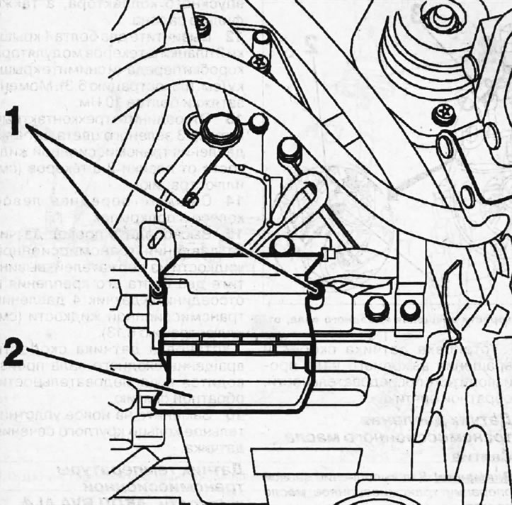
6.3. Unscrew the two bolts 1 of the cover 2 of the gearbox modulator connector strip and remove the…

6.3. Unscrew the two bolts 1 of the cover 2 of the gearbox modulator connector strip and remove the cover


4. Disconnect the yellow three-pin connector 4 of the input shaft speed sensor from the connector strip (see illustration).
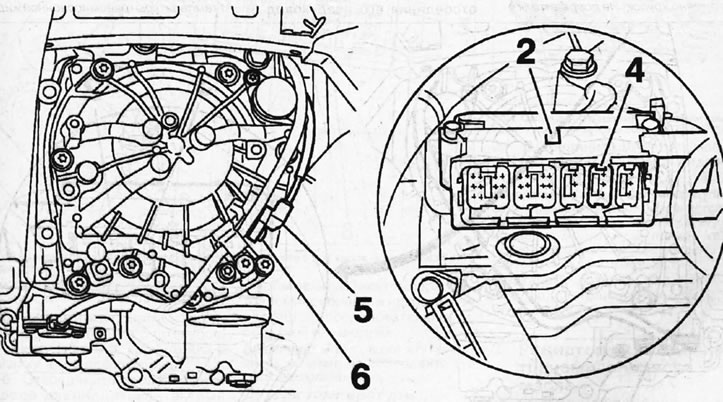
6.4. Disconnect the yellow three-pin connector 4 of the input shaft speed sensor from the connector…

6.4. Disconnect the yellow three-pin connector 4 of the input shaft speed sensor from the connector strip


5. Remove the front left wheel and fender liner.

6. Release the wiring harness of the input shaft speed sensor from the holders, unscrew bolt 6 and remove the input shaft speed sensor 5 (see illustration 6.4).

Installation of the input shaft speed sensor is carried out in the reverse order of removal.

7. Replace the sensor O-ring with a new one.

Secondary shaft speed sensor


Removal


Important! There is no need to drain the transmission oil to perform this operation.


8. Remove the battery and front left wheel.

9. Unscrew bolt 1, remove output shaft speed sensor 2, disconnect its plug 3, releasing it from the holder (see illustration).
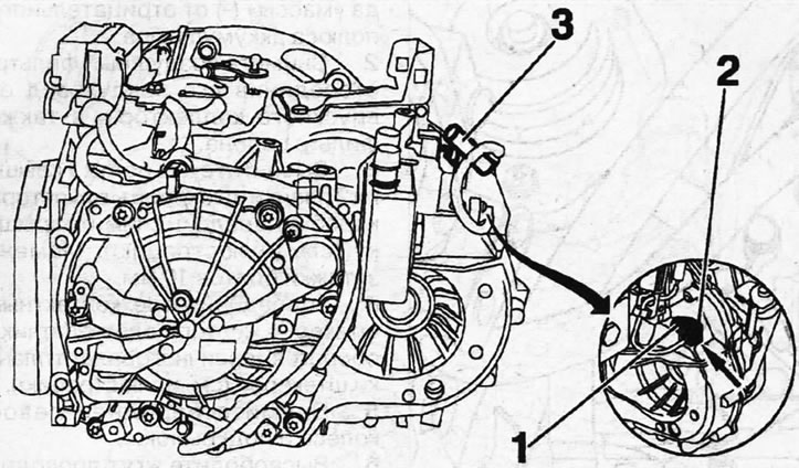
6.9. Unscrew bolt 1, remove output shaft speed sensor 2, disconnect its plug 3

6.9. Unscrew bolt 1, remove output shaft speed sensor 2, disconnect its plug 3


Caution! The plug holder is quite fragile. Don't damage it


The output shaft speed sensor is installed in the reverse order of removal.

Transmission oil pressure sensor


Removal


Important! There is no need to drain the transmission oil to perform this operation.


10. Disconnect the negative (-) battery terminal from the battery.

11. Remove the air filter by disconnecting its air duct from the intake manifold, as well as the cabin filter.


12. Unscrew the two bolts 1 of the cover 2 of the gearbox modulator connector strip and remove the cover (see illustration 6.3). Tightening torque of bolts 10 Nm.

13. Disconnect the green three-pin connector 3 of the transmission fluid pressure sensor from the connector strip 2 (see illustration).
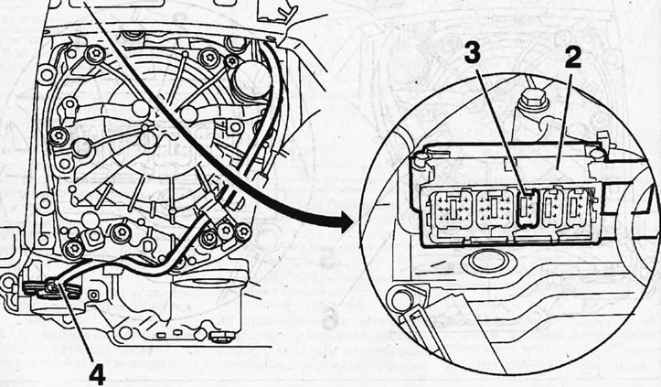
6.13. Disconnect the green three-pin connector 3 of the transmission fluid pressure sensor from the…

6.13. Disconnect the green three-pin connector 3 of the transmission fluid pressure sensor from the connector strip 2


14. Remove the front left wheel and fender liner.

15. Release the transmission fluid pressure sensor wire from the holders, unscrew the two bolts securing it and disconnect the transmission fluid pressure sensor 4 (see illustration 6.13).

Installation of the input shaft speed sensor is carried out in the reverse order of removal.

16. Replace the sensor O-ring with a new one.

Transmission fluid temperature sensor. Automatic transmission BVA AL4


Removal


17. Remove the modulator.
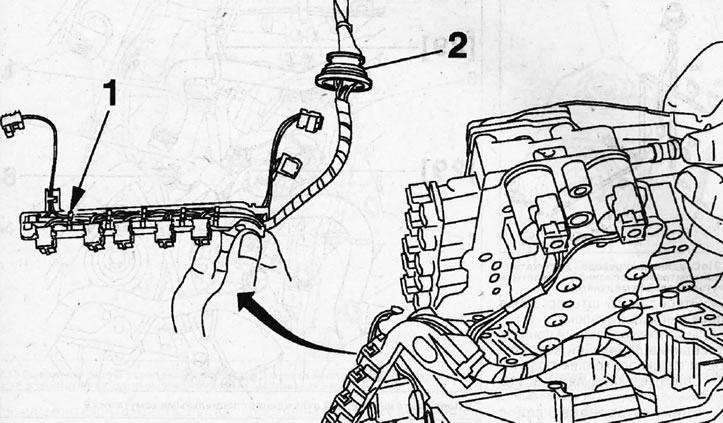
6.17 Transmission fluid temperature sensor and its wire in the modulator wiring harness. Automatic…

6.17 Transmission fluid temperature sensor and its wire in the modulator wiring harness. Automatic transmission BVA AL4


Caution! If you replace the transmission fluid temperature sensor 1, the modulator wiring harness must also be replaced (see illustration 6.17).


18. Unscrew the two bolts that secure the 5-plug bar, as well as the two bolts of the 6-bar bracket (see illustration).
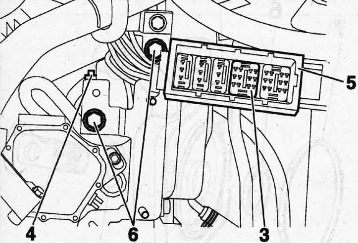
6.18. Unscrew the two bolts that secure the 5-plug bar, as well as the two bolts of the 6-bar…

6.18. Unscrew the two bolts that secure the 5-plug bar, as well as the two bolts of the 6-bar bracket


19. Disconnect the yellow twelve-pin connector 3 of the transmission fluid temperature sensor from the connector strip, remove the holder 4 and disconnect the modulator wiring harness (see illustration 6.18).

The transmission fluid temperature sensor is installed in the reverse order of its removal.

Caution! When installing the modulator wiring harness, maintain its original position.


Transmission fluid temperature sensor. 4HP20 AT


Removal


20. Remove the modulator.

21. Disconnect the transmission fluid temperature sensor 1 (see illustration).
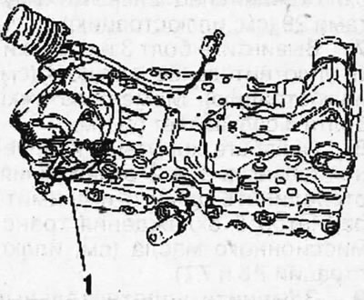
6.21. Disconnect the transmission fluid temperature sensor 1. 4HP20 AT

6.21. Disconnect the transmission fluid temperature sensor 1. 4HP20 AT


Caution! If the coolant temperature sensor is replaced, the entire modulator wiring harness must be replaced, because wire 1 of the sensor is connected to the harness (see illustration 6.21a).
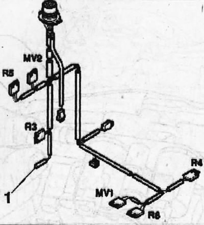

6.21a. Connecting wire 1 of the transmission fluid temperature sensor to the modulator wiring…

6.21a. Connecting wire 1 of the transmission fluid temperature sensor to the modulator wiring harness


The sensor is installed in the reverse order of its removal.
This article is available at russian, bulgarian, belarusian, ukrainian, serbian, croatian, romanian, polish, slovak, hungarian
Article reviewed by editor: Vinogradov Robert
Share information:
Previous
Peugeot 807: Automatic gearbox
Next

Torque converter — removal and installation
Transmission oil — checking the level, replacement
Gearbox — removal and installation
Automatic transmission — general information
Automatic transmission specifications
Transmission Oil Cooler — Removal and Installation
See similar information for other Peugeot models

➨ Camshaft Position Sensors (EP Series Gasoline Engines) Peugeot 207 (2006-2014)
➨ Engine and gearbox — removal Peugeot 305 (1977-1989)
➨ Checking the gearbox oil level (60,000 km/3 years) Peugeot 405 (1987-1997)
➨ Checking the transmission fluid level in the gearbox Peugeot 605 (1989-2000)
Link to this article in different formats
Comments and feedback from visitors
No comments yet


Add two numbers 44 + 35


Partner I (1996-2008) 
  • General information
  • Introduction to the guide
  • Faults en route
  • Weekly checks
  • User manual
  • Maintenance (petrol)
  • Maintenance (diesel)
  • Power unit
  • Petrol engines
  • Diesel engines «XUD»
  • Diesel engines «DW»
  • Overhaul of petrol engines
  • Overhaul of diesel engines
  • Cooling and heating
  • Power and exhaust (petrol)
  • Power and exhaust (XUD diesels)
  • Power and exhaust (DW diesels)
  • Emission reduction
  • Starting and charging system
  • Transmission
  • Clutch
  • Mechanical gearbox
  • Drive shafts
  • Chassis, running gear
  • Brake system
  • Car suspension
  • Steering
  • Body and interior
  • Exterior (external elements)
  • Interior (internal elements)
  • Doors, locks and windows
  • Electrical equipment
  • Equipment and devices
  • Electrical circuits
Peugeot 807 (2002-2014) 
  • General information
  • Operating instructions
  • Maintenance
  • Troubleshooting
  • Power unit
  • Gasoline engines
  • Diesel engines
  • Cooling and heating
  • Fuel injection (petrol)
  • Fuel system (diesel)
  • Fuel system
  • Exhaust system
  • Ignition system
  • Transmission
  • Clutch
  • Manual gearbox
  • Automatic gearbox
  • Chassis, running gear
  • Brake system
  • Car suspension
  • Steering system
  • Body and interior
  • Exterior (external elements)
  • Interior (internal elements)
  • Electrical equipment
  • Power devices
  • Electrical circuits
Peugeot 806 (1994-2002) 
  • General information
  • User manual
  • Maintenance
  • Power unit
  • Petrol engines
  • Diesel engines
  • Lubrication system
  • Cooling system
  • Fuel injection (petrol)
  • Fuel system (diesel)
  • Ignition and exhaust systems
  • ECM Bosch Motronic MP 3.2
  • ECM Magneti-Marelli (MM)
  • Transmission
  • Clutch
  • Mechanical gearbox
  • Chassis, running gear
  • Brake system
  • Car suspension
  • Steering
  • Electrical equipment
  • Equipment and devices
  • Electrical circuits
Peugeot J5 (1981-1993) 
  • General information
  • Introduction to manual
  • Specifications
  • Gasoline engine
  • Engine repair
  • Lubrication system
  • Cooling system
  • Fuel system
  • Ignition system
  • Diesel engine
  • Engine repair (DB9)
  • Lubrication system (DB9)
  • Cooling system (DB9)
  • Fuel injection (DB9)
  • Engine repair (U25)
  • Lubrication system (U25)
  • Cooling system (U25)
  • Fuel injection (U25)
  • Transmission
  • Clutch
  • Gearbox
  • Drive shafts
  • Chassis, running gear
  • Steering system
  • Car suspension
  • Brake system
  • Electrical equipment
  • Power devices
  • Electrical circuits
PeugeotBook.ru © 2018–2026 | Mobile version | Sitemap: EN BG BY UA RS HR RO PL SK HU | Write message | Site search | Add to bookmarks | Peugeot owners
106 (1991-2003) | 206 (1998-2012) | 207 (2006-2014) | 305 (1977-1989) | 306 (1993-2002) | 307 (2001-2008) | 405 (1987-1997) | 406 (1995-2004) | 605 (1989-2000) | Partner-I (1996-2008) | Eurovans-807 (2002-2014) | Eurovans-806 (1994-2002) | J5 (1981-1993) |
Cookies are used to ensure the correct display of pages on the site.