



Table of contents: 14.3.1. Checking the starter 🠇 14.3.2. Removing and installing the…🠇 14.3.3. Disassembling and assembling…🠇
Cars may be equipped with starters from Ducellier, Paris-Rhone or Bosch, depending on what units were available at the time of the car's production. The starter is activated by a traction relay, connecting to the battery. At the same time, the traction relay moves the gear with the overrunning clutch along the axis to the flywheel ring gear. The starter begins to turn the engine only after the pinion engages with the flywheel ring gear. When the engine starts and reaches speeds greater than the starter speed, the overrunning clutch in the gear engages, preventing the starter armature from reaching higher speeds, thus protecting the starter.
14.3.1. Checking the starter
To check the starter under full battery voltage, short-circuit terminal "30" (large terminal on the Bosch starter) with terminal "50" (contact to the right of the large terminal) wire with a cross-section of at least 4.0 mmg.
If the starter works normally, check the electrical connection diagram of the starter. If the starter does not turn on, it should be removed and checked.
A thorough check of the starter can only be carried out on a test bench in a workshop.
14.3.2. Removing and installing the starter
- Disconnect the ground wire from the battery.
- Raise the front of the car.
- Disconnect the wires from the traction relay and starter.
- Loosen the mounting bolts and nuts.
- Pull out the starter.
The starter is installed in reverse order. First, press the starter firmly against the mounting flange on the clutch housing before tightening both bolts.
Connect the battery and check the operation of the starter.
14.3.3. Disassembling and assembling the starter
Below is a more detailed description of work with the Bosch starter, which is installed on most cars. Figure 204 shows the installation drawing of this starter.
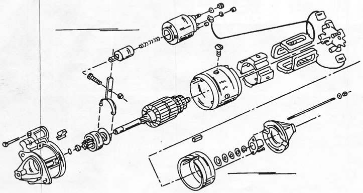
Figure 204. Installation drawing of the Bosch starter.
- Loosen the screws on the front side of the traction relay and, to remove the relay, disengage the starter drive engagement lever.
- Unscrew and remove the cover from the rear of the starter.
- Unscrew the manifold bearing cover bolts.
- Use a screwdriver to press the locking bar from the end of the armature shaft, remove the small parts and pull the cover off the starter. If necessary, use a screwdriver to pry the cover open. Save the inserted washers.
- Remove both carbon brushes from their mounts and remove the brush holder.
- Remove the housing with the stator windings.
- Remove the starter drive engagement lever support pin and take out the lever.
- Remove the gasket from the bearing shield, remembering its installation position.
The stator winding brushes are soldered to the windings and can only be replaced together with the windings when replacing the entire coil. When making this replacement, the following work must be performed:
- Loosen the four pole piece screws by tapping their slots with a brass rod as shown in Figure 205.
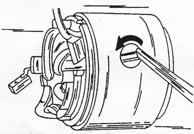
Figure 205. Loosening the pole piece screws with a brass rod.
- Remove the pole pieces and release the winding with brushes from the pole pieces.
- When removing the anchor or starter gear, use Figure 206:
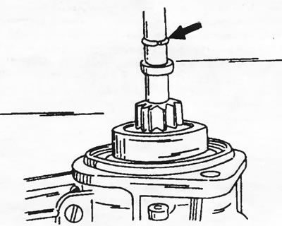
Figure 206. The arrow indicates the starter drive retaining ring. First, you need to knock down the tide ring.
- Knock down the thrust ring with a piece of pipe of the appropriate diameter to release the retaining ring indicated by the arrow in the figure.
- Remove the retaining ring from the groove of the armature shaft.
- Remove burrs from the end of the armature shaft.
- Clamp the armature in a vice and pull the drive gear off the armature shaft as shown in Figure 207.
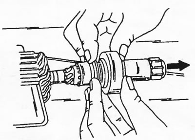
Figure 207. Removing the starter drive gear from the armature shaft.
Clean with gasoline (except for the stator winding, if it will be reinstalled) and check all the details. Check the anchor for burnt turns and the commutator for smooth surface. The collector can be processed with fine sandpaper, but a heavily worn collector is turned on a lathe while maintaining the minimum permissible diameter. A service station can do this work or recommend replacing the starter.
The starter gear cannot be disassembled and must be replaced if damaged.
The starter is assembled in reverse order. It should be noted that the minimum permissible length of carbon brushes is 13 mm. When replacing brushes, crumble the old brush with pliers and clean the brush current lead. Insert the current lead into the new brush and flatten it on the other side. Press the bottom side of the current lead with tweezers and solder its top side.
The following points should be especially taken into account:
- Slide the starter gear onto the shaft, put on the thrust ring and install a new retaining ring on the shaft. Place the thrust ring on the press table (Figure 208) and press the spacer ring into the thrust ring, applying press force to the armature shaft.
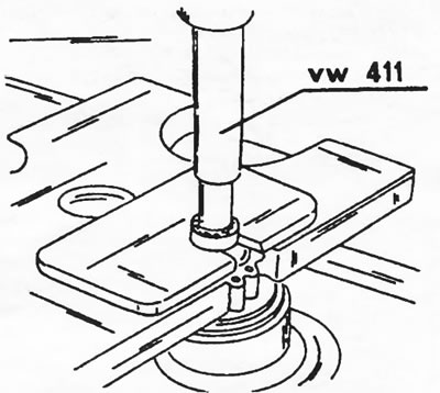
Figure 208. Pressing the thrust ring over the anchor shaft retaining ring.
- If the bushing in the manifold shield needs to be replaced (it can simply be pressed out), the new bushing should be pressed in after preheating the bearing cap in hot oil.
- When installing the traction relay, ensure normal engagement of the pusher with the starter drive engagement lever.
- Cover the areas shown in Figure 209 with sealing compound.
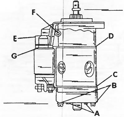
Figure 209. Before assembly, cover the areas marked with letters with sealing compound.
- The permissible axial play of the anchor is 0.1 - 0.3 mm, which can be adjusted by changing the thickness of the compensating washers installed between the end of the sleeve in the collector cover and the C-shaped lock washer.
Ducellier starter
The installation drawing of this starter is shown in Figure 210; it can be used in dismantling work. When replacing the brushes, they must be unsoldered. To do this, you have to remove the anchor and the cover.
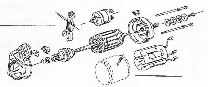
Figure 210. Ducellier starter assembly drawing.
Further disassembly is carried out as follows:
- Remove the starter housing.
- Unscrew the traction relay.
- Knock out the pin from the starter drive engagement lever. The pin is knocked out from right to left when looking at the end of the starter drive.
- Remove the anchor from the drive bearing shield. Immediately check the condition of the anchor. Wipe the collector with a rag soaked in gasoline, being careful not to let gasoline get on the winding. If the collector is very dirty, it can be treated with fine sandpaper. The skin should not be used in this case.
- If there are burnouts on the collector, it can be ground down. This work should be entrusted to a service station, since it is necessary to maintain the minimum permissible collector diameter.
- Saw slots in the starter lamellas with a thin file to a depth of 0.5 mm.
- Check the movement of the starter pinion and replace the pinion if necessary. To do this, remove the retaining ring from the armature shaft after using a piece of pipe of the appropriate diameter to move the retaining ring towards the armature, as described for the Bosch starter.
- Check the carbon brushes and replace them if necessary. As already mentioned, they must be unsoldered from the windings when replaced.
- Lubricate the front bushing before assembly.
- Install the anchor and traction relay into the drive bearing shield. The support pin of the starter drive engagement lever is driven in from the left side of the shield.
- Fill the rear bushing with grease and put on the cover. Ensure proper engagement of the springs.
- When securing the cover, place the washers in the same order and tighten the bolt. The starter overrunning clutch does not require adjustment.
- Install both tie bolts.
(Original published on the portal PeugeotBook)