



Table of contents: 14.2.1. Precautions when working…🠇 14.2.2. Checking the alternator…🠇 14.2.3. Removal and installation 🠇 14.2.4. Repair of the alternator 🠇 14.2.5. Paris-Rhone AC generator 🠇
14.2.1. Precautions when working with the battery charging circuit
Before working on the battery charging circuit, be sure to remember the following safety precautions:
- Never disconnect the battery or voltage regulator while the engine and therefore the generator are running.
- Do not allow contact with the generator excitation terminal ground or the wire connected to this terminal.
- Do not swap the voltage regulator wires.
- Do not turn on the voltage regulator if it is connected to ground (instant failure).
- Do not remove the generator without first disconnecting the battery from the vehicle's electrical system. Otherwise, irreparable equipment failure may occur.
- When installing the battery, be careful when connecting the negative battery terminal to ground (don't confuse the poles).
- Do not use a mains powered test lamp (110 or 220 volts). Use only a 12 volt lamp.
- When charging a battery installed in a vehicle using a charger, be sure to completely disconnect the battery from the vehicle's electrical system. Connect the positive terminal of the charger to the positive pole of the battery, and the negative terminal of the charger to the negative pole of the battery.
- Incorrect connection of wires causes failure of the rectifier and voltage regulator.
- When replacing an alternator, purchase the correct type of alternator.
14.2.2. Checking the alternator installed on the vehicle
Under normal operating conditions while driving, the charge indicator lamp should not light. If it lights up, the cause may be a defect in the generator or voltage regulator.
Check and, if necessary, adjust the V-belt tension.
If you have a voltmeter, ammeter and a resistance box, you can carry out the following tests by assembling the test circuit in accordance with Figure 192.
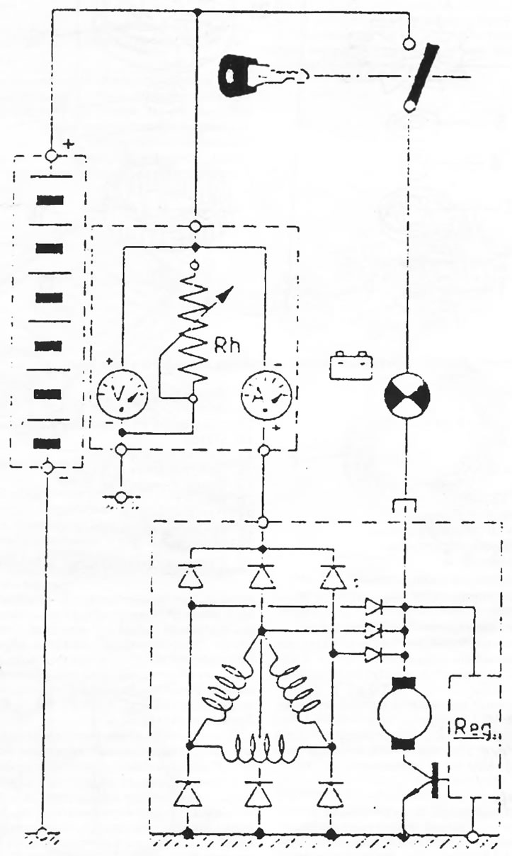
Figure 192. Circuit for checking the voltage and current of the alternator.
- Disconnect the ground wire from the battery.
- Disconnect the excitation wire from the EXC terminal of the alternator and the charging circuit wire from the positive terminal.
- Connect an ammeter in series and a resistance box in parallel to the charging circuit. The positive terminal of the ammeter should be connected to the "+" terminal of the alternator, and the negative terminal should be connected to the disconnected charging circuit wire. The resistance box must be connected between the negative terminal of the ammeter and ground.
- Connect a voltmeter in parallel to the charging circuit. The positive terminal of the voltmeter should be connected to the "+" terminal of the alternator, and the negative terminal connected to ground.
- Connect the ground wire to the battery.
- Connect the speed meter in accordance with the manufacturer's operating instructions.
- Start the engine and let it run at idle speed. Check that the engine speed is at least 700 rpm and adjust the resistance on the battery pack until the voltmeter reading reaches 14 volts. The ammeter reading should be at least 16 amps.
- Increase the engine speed to 900 rpm and check whether the ammeter reading increases to 32 amps. A further increase in engine speed to 1800 rpm should cause the ammeter reading to increase to 47 amps.
- Turn off the engine and disconnect the ground wire from the battery.
- Disconnect all devices and reconnect the generator wires. Connect the ground wire to the battery.
- The regulator voltage is checked on the same circuit. Increase the speed to 1800 rpm and take readings from the voltmeter and ammeter. At a current of 42 amperes, the voltage should be 13.8 - 14.5 volts.
14.2.3. Removal and installation
- Disconnect the ground wire from the battery.
- Disconnect the connector from the rear of the alternator. Disconnect the wire from the disconnected terminal.
- Loosen the belt tension as described in the "Cooling System" section (depending on the installed units) and remove the belt.
- Loosen and remove the two generator mounting bolts from the bottom.
- Remove the generator. This may require raising the vehicle.
The generator is installed in reverse order. Install and tighten the V-belt as described in the "Cooling System" section (section 4.4.).
14.2.4. Repair of the alternator
Without the necessary experience, it is prohibited to repair the alternator and the associated voltage regulator. A failed generator can be exchanged at the exchange fund. Minor repairs, such as replacing carbon brushes, can be done in a workshop.
The alternator has lifetime lubricated bearings and requires no regular maintenance. The outside of the generator must be clean and no water or solvents must enter it.
The generator brushes work with a smooth commutator and therefore have a long service life. To check the condition of the brushes, it is necessary to remove the alternator. Below is a description of the disassembly and inspection of the Valeo alternator as installed on most vehicles.
Disassembly
Figure 194 shows the installation drawing of the generator.
- Remove the nut from the rotor shaft and remove the belt pulley, fan and spacer washer from the shaft. When removing the shaft, it is necessary to hold it by placing an old V-belt on the pulley and clamping the pulley in a vice, as shown in Figure 193. You can also insert a rod wrench into the hexagon of the shaft when unscrewing the nut. To remove the belt pulley, you will need a puller with two or three jaws.
- Remove the key from the shaft.
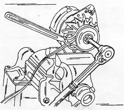
Figure 193. Loosening the nut on the inside of the belt pulley. Place the V-belt on the pulley.
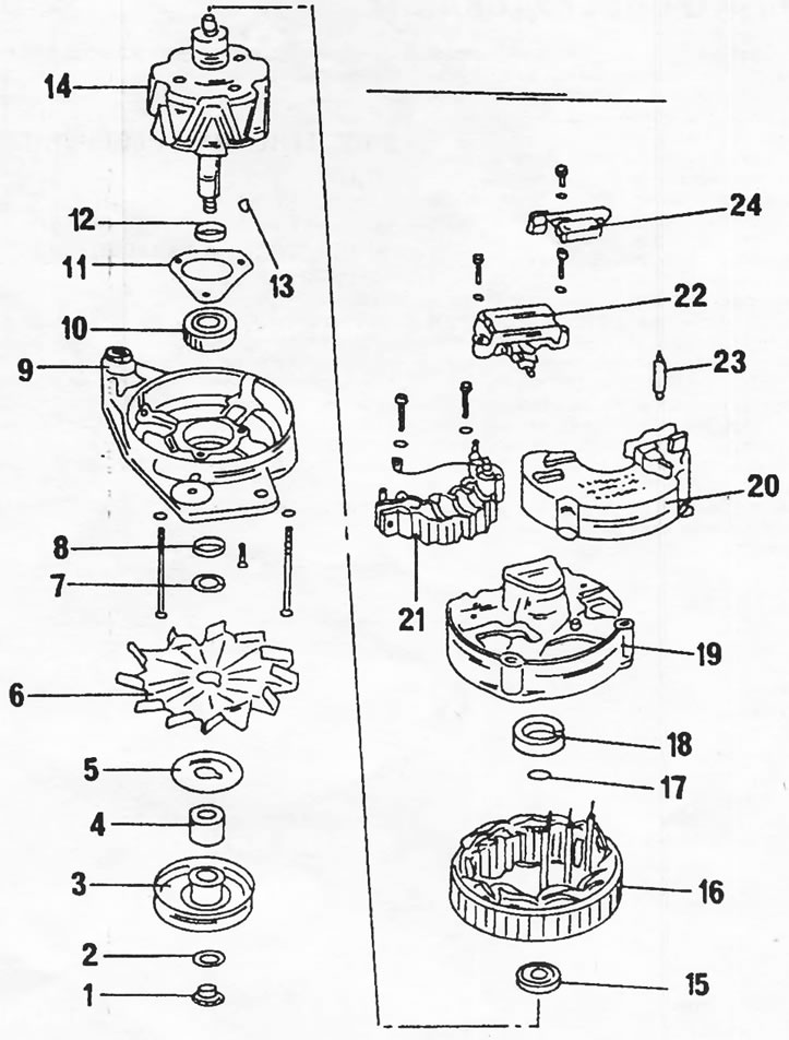
Figure 194. Installation drawing of the Valeo alternator. 1. Nut, 40 nm; 2. Washer; 3. Belt pulley, 70 Nm; 4. Expansion sleeve; 5. Washer; 6. Fan; 7. Washer; 8. Spacer ring; 9. Drive bearing shield; 10. Drive side bearing; 11. Bearing mounting plate; 12. Spacer ring; 13. Key; 14. Rotor; 15. Bearing on the carbon brush side; 16. Stator; 17. Metal ring; 18. Plastic bushing; 19. Generator housing; 20. Lid; 21. Board with diodes; 22. Voltage regulator; 23. Hairpin; 24. Radio interference suppression capacitor
Unscrew and remove the voltage regulator together with the brush holder.
- Mark the drive bearing shield and the generator housing on opposite sides and unscrew both studs from the housing. Separate the rear bearing cover from the front. Lightly tap the front cover with a plastic hammer.
- Place the bearing shield and rotor under a press and remove the rotor using a three-jaw puller, as shown in Figure 195. When pressing out the rotor, the bearing mounting plate screws are stripped. Therefore, it is imperative to ensure that the puller jaws are installed under the bearing mounting plate, and not just under the bearing shield. If you need to remove the bearing from the shield, unscrew the screws from the inside and press out the bearing.
- Press out the bearing from the carbon brush side. If using a puller, position it under the inner bearing race.
- Unsolder the board with diodes from the stator.
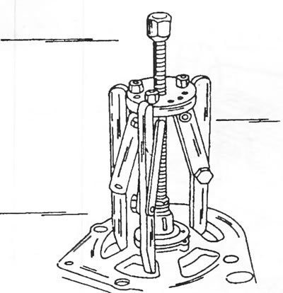
Figure 195. Removing the rotor using a three-jaw puller.
At the same time, hold the wires at the soldering points with tweezers, which serve as a heat sink. Do not allow the diodes to overheat.
Rectifier diodes can only be removed if you have the appropriate tools and the necessary knowledge.
Checking the carbon brushes and brush holder
Check the contact of the brushes with the commutator rings. Check the mobility of the brushes in the guides; if necessary, clean the guides with Tri.
If the protruding length of the brushes is less than 5.0 mm (Figure 196), new brushes should be soldered in. When the brushes approach this size, they should also be replaced to save on one generator disassembly. Use a ruler for measurements.
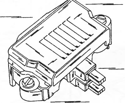
Figure 196. The ends of the brushes must protrude at least 5 mm.
Checking the rotor
If the commutator rings are dirty or oily, wipe them with a cloth soaked in Tri. Polish any scratches with fine sandpaper. To check the insulation, connect one end of the ohmmeter to the rotor core and the other to the collector rings. If the ohmmeter reading is different from "infinity", the rotor should be replaced. The measurement is carried out as shown in Figure 197.
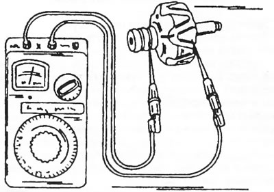
Figure 197. Rotor winding insulation testing diagram. Connect one end of the ohmmeter to the rotor core and the other to the collector rings.
The rotor winding resistance is checked by connecting both ohmmeter wires to the collector rings. The resistance should be between 3.4 and 3.7 mm. If the resistance is "infinity," there is an open circuit in the winding. If the reading is zero, there is a short circuit in the winding. In both cases, the rotor must be replaced. The measurement is carried out as shown in Figure 198.
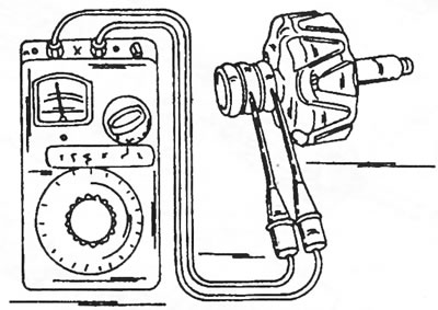
Figure 198. Checking the rotor winding resistance. The ohmmeter wires are connected to the collector rings.
Checking the stator
In the case of a short circuit, which is usually the result of severe overheating, the location of the damage is already revealed during an external inspection. Otherwise, connect one ohmmeter lead to the stator lamellar ring and connect the other end in series to each of the three stator winding wires, as shown in Figure 199. The ohmmeter reading should be "infinity" in all measurements. To check the stator winding resistance, connect the ohmmeter leads in series to two of the three winding wires, as shown in Figure 200. If there is no reading, the winding is open. The resistance should be 0.10-0.11 ohms.
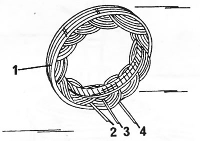
Figure 199. Checking stator windings for short circuits. Connect the ohmmeter to the lamellar ring (1) and in series to the wires of windings 2, 3 and 4. The resistance should be equal to infinity.
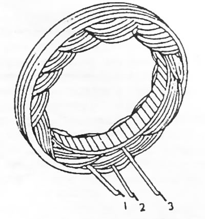
Figure 200. Connect an ohmmeter in series to the ends of windings 1 and 2, 1 and 3, and 2 and 3. The resistance should be equal to the values given in the text.
(The source is located on the website: «PeugeotBook.ru»)
Checking diodes
Accurate testing of the electrical characteristics of diodes requires a special test device and should only be performed in a workshop.
Assembly
Figure 194 shows the installation drawing of the Valeo generator; when assembling, please use this drawing.
14.2.5. Paris-Rhone AC generator
As mentioned earlier, Paris-Rhone alternators were also installed on cars during production. Figure 201 shows the installation drawing of this alternator.
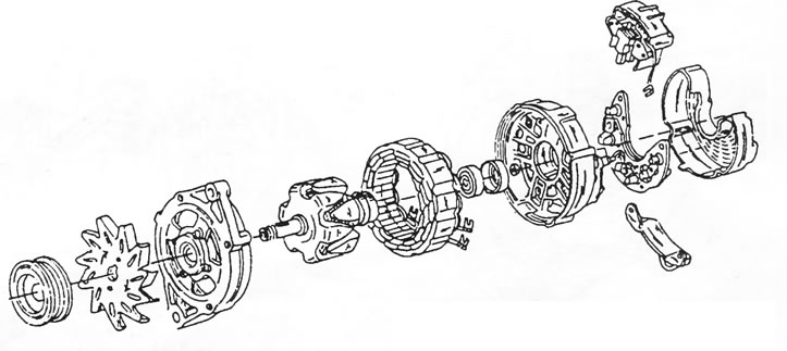
Figure 201. Assembly drawing of the Paris-Rhone alternator.
Disassembling the generator for the purpose of replacing brushes or bearings is carried out as follows:
- Unscrew the two voltage regulator screws and remove the regulator.
- Carefully clamp the generator in a vice and insert a wrench of the appropriate size into the generator shaft. Loosen the shaft nut. Remove the belt pulley, spacer washer, key and flange washer from the front end of the shaft.
- Remove the long through bolts from the front of the generator.
- Use a screwdriver to pry the front bearing shield away from the stator housing. Insert a screwdriver into the location shown in Figure 202, but no deeper than 2.0 mm to avoid damaging the stator winding. Remove the drive bearing shield together with the bearing located in it.
- To replace the bearing, remove the four screws from the front of the bearing shield. After this, take hold of the shield and bearing as shown in Figure 203 and hit the shaft on a piece of wood. In this case, the bearing is released from the rotor.
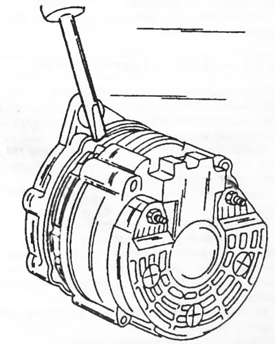
Figure 202. Pressing the drive bearing shield away from the generator.
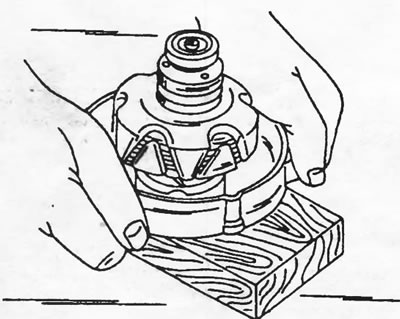
Figure 203. Separating the rotor from the bearing shield.
Further disassembly is not recommended.
The generator is assembled in reverse order. The length of the brushes is measured in the same way as on other generators. The brushes also protrude from the voltage regulator. Soldering in new brushes is not easy, so it is better to entrust this work to a workshop or install a new voltage regulator.