



Table of contents: Cylinder head 🠇 Valve seats 🠇 Valves 🠇 Camshaft 🠇 Pistons and connecting rods 🠇 Crankshaft and flywheel 🠇
Cylinder head
Cylinder head height: 140.00±0.15 mm
Minimum permissible cylinder head height is 139.55 mm
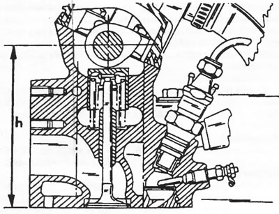
The maximum permissible distortion of the cylinder head surface is 0.03 mm
Milling of the cylinder head surface is not permitted
Cylinder head gasket thickness
- normal, during car production - 1.49 mm,
- when replacing - 1.61 mm
- increased size - 1.73 mm
Valve head dimension below cylinder head surface:
- Inlet valves - 0.5-1.05 mm
- Exhaust valves - 0.9-1.45 mm
Original is located at www.PeugeotBook.ru
Valve guide bushings
- Nominal diameter: 14.02 mm
- 1st repair size - 14.29 mm
- 2nd repair size - 14.59 mm
Guide bushing hole diameter: 8.02 mm (established position)
Installation height, head surface to bushing - 36.5±0.5 mm
Cylinder head bore diameter:
- Nominal diameter: 13.981 mm
- 1st repair size - 14.211 mm
- 2nd repair size - 14, 511 mm
- tolerance - + 0.032 mm
Valve seats
Valve seat angle - 90°
Valve seat width - inlet/outlet - 2.45/3.00 mm
Replacement of valve seat rings is performed in the workshop
Valve seat diameter:
- Intake valves - 40.161 mm
- Exhaust valves - 34.137 mm
Valves
Valve seat angle - 45° (full angle 90o)
Valve head diameter:
- Inlet valves - 38.50±0.2 mm
- Exhaust valves - 33.00±0.2 mm
Overall length:
- Intake valves - 112.40+0.3 mm
- Exhaust valves - 111.85±0.3 mm
Valve stem diameter:
- Intake valves - 8.005 mm
- Exhaust valves - 7.985 mm
- The maximum permissible grinding of the valve stem end is 0.20 mm
- The minimum allowable width of the valve edge is 0.50 mm
Valve stem clearances in the holes:
- Inlet valves - 0.015-0.045 mm
- Exhaust valves - 0.045-0.075 mm
- Maximum valve clearance in the guide bushing is 0.10 mm
Valve springs
Wire diameter: 3.8 mm
Length in free state - 51.00 mm
Spring markings - Intake and exhaust valve springs are identical
Cylinder head marked "R" - a 0.4 mm thick washer is placed under the spring
Camshaft
Number of bearings - 3
Axial clearance of the camshaft is 0.07–0.17 mm
Bearing journal diameter:
- bearing No. 1 (from the flywheel side) — 27.50 mm
- bearing No. 2 - 28.00 mm
- bearing No. 3 (from the timing drive side) — 28.50 mm
Bearing holes in the cylinder head are +0.033 mm larger
Camshaft marking - Colored ring on cam of cylinder 1
Pistons and connecting rods
Piston pin installation - Floating in the connecting rod bore and in the piston
Piston Installation - See "Pistons and Connecting Rods" section in the main text
Piston rings:
- Number of rings - 3
- Ring design - 1 regular compression ring, 1 trapezoidal ring, 1 oil-deflecting ring
Piston ring thickness:
- top ring - 2.0 mm
- middle ring - 2.00 mm
- oil deflector ring - 3.0 mm
Piston ring joint clearances nominal dimensions —
- upper compression ring - 0.20-0.40 mm
- middle upper compression ring - 0.15-0.35 mm
- oil deflector ring - 0.25-0.50 mm
Piston diameter:
- nominal diameter - 82.930±0.009 mm
- increased size 1 - 83.130±0.009 mm (at the bottom of the piston "R1")
- increased size 2 - 83.430±0.009 mm (at the bottom of the piston "R2")
- increased size 3 - 83.730±0.009 mm (at the bottom of the piston "R3")
Cylinder bore diameter:
- nominal diameter - 83.00 + 0.018 mm
- increased size 1 - 83.20 + 0.018 mm (on the piston bottom "R1")
- increased size 2 - 83.50 + 0.018 mm (on the piston bottom "R2")
- increased size 3 - 83.80 + 0.018 mm (on the bottom of the piston "R3")
Piston clearances: 0.062–0.078 mm
Piston Protrusions/Cylinder Head Gaskets:
- Protrusion - Cylinder head gasket
- 0.54 - 0.65 mm - 1.49 mm
- 0.65 - 0.77 mm - 1.61 mm
- 0.77 - 0.82 mm - 1.73 mm
Cylinder head gasket markings:
- 1 cutout in the gasket for the protrusion - 0.54-0.65 mm
- 2 cutouts in the gasket for the protrusion - 0.65-0.77 mm
- 3 cutouts in the gasket for the protrusion - 0.77-0.82 mm
The maximum permissible difference between the protrusions of the highest and lowest pistons is 0.12 mm
Piston pin diameter: 25.0 - 0.006 mm
Piston pin length: 72.00 mm
Connecting rod bore diameter: 25.00 + 0.020 mm
Piston pin hole - 25.00 + 0.008 mm
Connecting rods and connecting rod bearings:
- design - conventional bearing shells
- material - aluminum-zinc alloy
- diameter of connecting rod journals - cm. "Crankshaft"
Connecting Rod Bore - See above
Connecting rod bearing bore: 53.695 mm
Connecting rod length, center to center: 145.0 + 0.025 mm
Crankshaft and flywheel
Number of bearings - 5
Main bearing shells:
- design - Conventional bearing shells, with or without lubrication grooves, to be marked before removal
- material - aluminum-zinc alloy
Crankshaft axial play: 0.07–0.32 mm
Thickness of expansion washers:
- nominal size - 2.30 mm
- increased sizes - 2.40, 2.45 and 2.50 mm
Main journal diameter - all engines:
- nominal diameter - 60,000 mm - 0.019 mm
- repair diameter - 59.700 mm - 0.019 mm
Bearing hole in the engine crankcase (the lid is installed):
- nominal diameter - 63.750 mm
The maximum permissible ovality of the necks is 0.007 mm
Main bearing shells:
- nominal thickness - 1.842 mm
- repair size (white mark on the edge) — 1,992 mm
Main journal diameter:
- nominal diameter - 50.0 mm - 0.016 mm
- repair size - 49.70 mm - 0.016 mm
- connecting rod bearing shells - nominal thickness - 1.827 mm
- repair size - 1.977 mm
Connecting rods:
- Connecting rod bushing bore: 25,000 mm
- Connecting rod bearing bore diameter: 53.965 mm
- Distance between centers: 145.0 mm
- The maximum weight difference on one engine is 4 g
- Maximum flywheel runout: 0.06 mm