



Note: A new lower column pinch-bolt and nut must be used on refitting.
Removal
1. Disconnect the battery negative terminal (refer to "Disconnecting the battery").
2. Remove the steering wheel as described in Section 10.
3. Unclip the front edge of the under-facia trim panel from the facia and lower the panel. Unscrew the two nuts securing the trim panel to the studs in the footwell, then withdraw the panel from the footwell (see illustration).
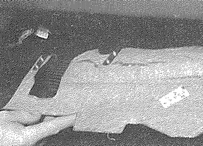
12.3. Withdraw the under-facia trim panel
4. Working under the steering column, remove the three steering column shroud securing screws. Unclip and lift off the upper shroud, then withdraw the lower shroud. Note that the lower shroud clips over a metal bracket on the steering column and the shroud must be slid from the bracket before it can be removed.
5. Working in the footwell, unscrew the securing nut from the lower column pinchbolt, then carefully tap the pinch-bolt from the universal joint. Pull off the metal clip securing the column to the steering gear pinion (see illustrations).
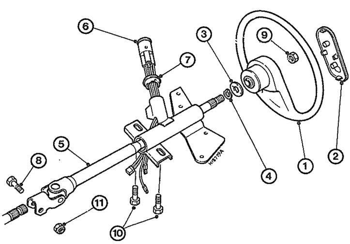
12.5a. Steering column and associated components 1. Steering wheel; 2. Centre pad; 3. Bowl washer; 4. Stop-ring; 5. Column; 6. Steering lock/ignition switch assembly; 7. Gasket; 8. Pinch-bolt; 9. Steering wheel securing nut; 10. Steering column securing bolts; 11. Pinch-bolt nut
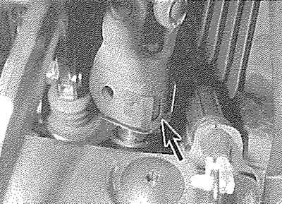
12.5b. Pull off the metal clip (arrowed) securing the column to the pinion
6. Make alignment marks on the universal joint and the steering gear pinion, then push the universal joint upwards to separate it from the pinion.
7. Disconnect the wiring plugs from the steering column combination switches.
8. Unclip the ignition switch wiring connectors from the steering column bracket or the facia, as applicable. Note the location of the connectors, so that they can be refitted in their original positions. Separate the two halves of each connector.
9. Ensure that all wiring has been moved clear of the column to facilitate removal.
10. Working under the steering column, unscrew the two steering column securing bolts, then lift the steering column from the facia and withdraw it from the vehicle.
Inspection
11. The steering column incorporates a telescopic safety feature. In the event of a front-end crash, the shaft collapses, reducing the chance of the steering wheel injuring the driver. Before refitting the steering column, examine the column assembly for signs of damage and deformation and renew as necessary.
12. Check the steering shaft for signs of free play in the column bushes and check the universal joints for signs of damage or roughness in the joint bearings. If any damage or wear is found on the steering column universal joints or shaft bushes, the column must be renewed as an assembly.
Refitting
13. Offer the steering column into position and refit the securing bolts. Tighten the bolts to the specified torque.
14. Reconnect the ignition switch wiring connectors and the combination switch wiring plugs. Fasten the ignition switch wiring connectors in position as noted before removal.
15. Refit the metal clip, then slide the column universal joint over the steering gear pinion, ensuring that the marks made before removal are still aligned.
16. Fit a new lower column pinch-bolt and nut, ensuring that the lugs on the bolt engage with the cut-outs in the universal joint. Tighten the nut to the specified torque.
17. Refit the steering column shrouds and the under-facia trim panel.
18. Refit the steering wheel as described in Section 10.
19. Reconnect the battery negative terminal.