



Table of contents: Manual steering gear 🠇 Power steering gear 🠇
Note: New track-rod end balljoint nuts and a new lower steering column pinch-bolt and nut must be used on refitting.
Manual steering gear
Removal
1. Ensure that the steering lock is engaged.
2. Unclip the front edge of the under-facia trim panel from the facia and lower the panel. Unscrew the two nuts securing the trim panel to the studs in the footwell, then withdraw the panel from the footwell.
3. Working in the footwell, unscrew the securing nut from the lower column pinch-bolt, then carefully tap the pinch-bolt from the universal joint. Pull off the metal clip securing the column to the steering gear pinion.
4. Make alignment marks on the universal joint and the steering gear pinion, then push the universal joint upwards to separate it from the pinion.
5. Chock the rear wheels then jack up the front of the vehicle and support it on axle stands (see "Jacking and vehicle support"). Remove the front roadwheels.
6. Working on each side of the vehicle in turn, unscrew the nut securing the track-rod end to the steering arm on the suspension strut and recover the washer. Using a balljoint separator tool, separate the track-rod end from the steering arm.
7. Working through the right-hand wheel arch, unscrew the three Torx bolts securing the steering gear to the engine compartment bulkhead (see illustration) and recover the washers. Withdraw the steering gear, complete with the track-rods, through the right-hand wheel arch.
Original published on the portal (www.peugeotbook.ru)
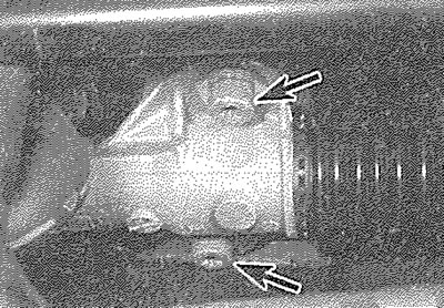
13.7. Two of the steering gear securing bolts (arrowed)
Overhaul
8. Examine the steering gear assembly for signs of wear or damage. Check that the rack moves freely throughout the full length of its travel, with no signs of roughness or excessive free play between the steering gear pinion and rack. It is possible to overhaul the steering gear assembly housing components,but this task should be entrusted to a Peugeot dealer. The only components which can be renewed easily by the home mechanic are the steering gear rubber gaiter, the track-rod balljoints and the track-rods. Steering gear rubber gaiter, track-rod balljoint and track-rod renewal procedures are covered in Sections 14, 17 and 18 respectively.
Refitting
9. Before refitting the steering gear, the rack must be centralised as follows.
10. Make a mark on the rack housing, corresponding with the centre-line of the steering gear securing bolt hole nearest the steering gear rubber gaiter.
11. Move the rack to its full extent of movement, so that the steering gear rubber gaiter is fully extended. Measure the distance from the mark made on the rack housing to the end of the steering gear rubber gaiter nearest the track-rod sleeve (see illustration). Call this dimension "Y".
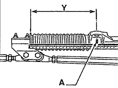
13.11. Steering rack centralisation -rack at maximum-travel position (left-hand drive steering gear shown) A. Mark on rack housing; Y. Maximum movement of rack - gaiter fully extended
12. Move the rack to its full extent of movement In the opposite direction, until the rubber gaiter is fully compressed. Again, measure the distance from the mark made on the rack housing to the end of the steering gear rubber gaiter nearest the track-rod sleeve (see illustration). Call this dimension "X".
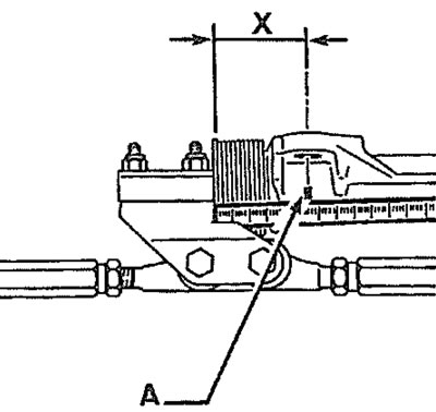
13.12. Steering rack centralisation -rack at minimum-travel position (left-hand drive steering gear shown) A. Mark on rack housing; X. Minimum movement of rack - gaiter fully compressed.
13. Calculate the dimension between the mark on the rack housing and the end of the steering gear rubber gaiter, which corresponds to the mid-position of the rack. Call this dimension "Z". Dimension "Z" can be calculated as follows:
- a) Subtract "X" from "Y" and divide the result by 2.
- b) Add "X" to the result of the previous calculation, to give dimension "Z". ie: Z=-(Y-X)/2 + X
14. Set the steering gear to dimension "Z", then proceed with the refitting procedure as follows, ensuring that the rack position is not altered during the refitting procedure.
15. Check the condition of the pinion shaft seal located in the engine compartment bulkhead. Ensure that the seal is correctly located and renew the seal if there are any signs of damage or wear.
16. Offer the steering gear into position through the right-hand wheel arch.
17. Check the routing of the clutch cable, making sure that the cable is not trapped between the steering gear and the track-rod.
18. Locate the steering gear on the bulkhead, ensuring that the dowels on the bulkhead engage with the corresponding holes in the steering gear.
19. Fit the steering gear securing bolts and tighten them to the specified torque.
20. Reconnect the track-rods to the steering arms, then fit the washers and new nuts and tighten the nuts to the specified torque.
21. Refit the metal clip and slide the column universal joint over the steering gear pinion, ensuring that the marks made before removal are still aligned.
22. Fit a new lower column pinch-bolt and nut, ensuring that the lugs on the bolt engage with the cut-outs in the universal joint. Tighten the nut to the specified torque.
23. Refit the under-facia trim panel.
24. Refit the roadwheels and lower the vehicle to the ground.
25. Have the front wheel alignment checked at the earliest opportunity (refer to Section 19 for details) and check that the steering wheel is centralised (if necessary, the steering wheel position can be altered by removing the wheel and moving it the required number of splines on the column shaft before refitting - see Section 10).
Power steering gear
Removal
26. Using suitable clamps, clamp both the fluid supply and return hoses near the power steering fluid reservoir. This will minimise fluid loss during subsequent operations.
27. Mark the unions to ensure that they are correctly positioned on reassembly, then unscrew the feed and return pipe union nuts from the steering gear assembly; be prepared for fluid spillage and position at suitable container beneath the pipes whilst unscrewing the union nuts. Disconnect both pipes and plug the pipe ends and steering gear orifices, to prevent fluid leakage and to keep dirt out of the hydraulic system.
28. Free the power steering pipes from any retaining clips and position them clear of the steering gear so that they will not hinder the removal procedure.
29. Remove the steering gear as described in paragraphs 1 to 7 inclusive.
Overhaul
30. Refer to paragraph 8, but additionally, inspect all the steering gear fluid unions for signs of leakage and check that all union nuts are securely tightened. Also examine the steering gear hydraulic ram for signs of fluid leakage or damage and if necessary renew it.
Refitting
31. Refitting is as described in paragraphs 9 to 25 inclusive, but additionally, note the following:
- a) Reconnect the fluid pipes to the steering gear, ensuring that they are correctly reconnected as noted before removal.
- b) Ensure that the pipes are repositioned correctly in any relevant clips and correctly routed to avoid straining the pipes.
- c) On completion, bleed the power steering hydraulic system as described in Section 15 and if necessary top-up the fluid level (see "Weekly checks").