



Table of contents: Fuel rail and injectors 🠇 Fuel pressure regulator 🠇 Throttle potentiometer 🠇 Electronic Control Unit (ECU) 🠇 Idle speed control stepper motor 🠇 Manifold absolute pressure (MAP)…🠇 Coolant temperature sensor 🠇 Inlet air temperature sensor 🠇 Crankshaft sensor 🠇 Fuel injection system relay unit 🠇 Knock sensor 🠇 Throttle housing heating element 🠇 Vehicle speed sensor 🠇
Fuel rail and injectors
1. On 8-valve engine models, refer to Section 13, paragraphs 1 to 9. On 16-valve engine models, remove the upper section of the inlet manifold as described in Section 15, then proceed as described in Section 13, paragraphs 1 to 9.
Fuel pressure regulator
2. Refer to Section 13, paragraphs 10 to 13.
Throttle potentiometer
3. Refer to Section 13, paragraphs 14 to 17 (see illustration).
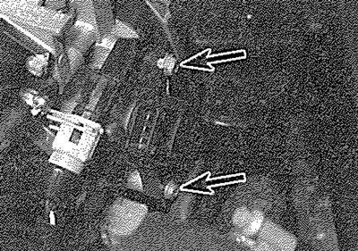
14.3. Throttle potentiometer retaining screws (arrowed)
Electronic Control Unit (ECU)
4. Refer to Section 13, paragraphs 18 to 20.
Idle speed control stepper motor
5. The idle speed control stepper motor is located on the top of the throttle housing assembly. To remove the motor, first disconnect the battery negative terminal (refer to "Disconnecting the battery").
6. Release the retaining clip and disconnect the wiring connector from the motor (see illustration).
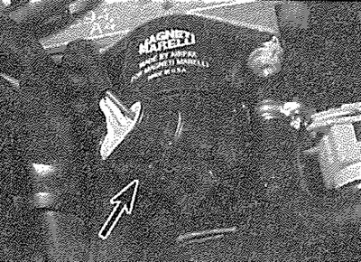
14.6. Disconnect the wiring connector (arrowed)...
7. Slacken and remove the two retaining screws and withdraw the motor from the throttle housing (see illustration).
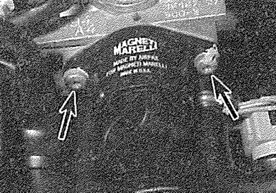
14.7. ... then undo the two screws (arrowed) and remove the stepper motor from the throttle housing
8. Refitting is a reversal of the removal procedure.
Manifold absolute pressure (MAP) sensor
9. The MAP sensor is mounted either on the engine compartment bulkhead, just behind the inlet manifold (see illustration), or alternatively it may be mounted directly on the inlet manifold casting. To remove the sensor, first disconnect the battery negative terminal (refer to "Disconnecting the battery").
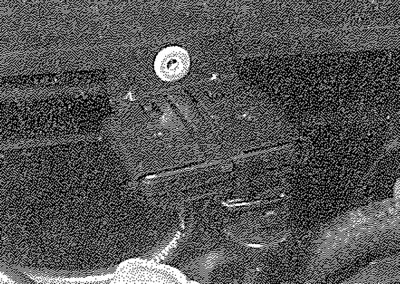
14.9. The MAP sensor is mounted on the engine compartment bulkhead
10. Where the sensor is mounted on the bulkhead, undo the retaining nut and free the sensor from its location. On some models, the sensor may be riveted to the bulkhead; if this is the case, drill out the rivet. Where the sensor is mounted on the inlet manifold, remove the securing screws and withdraw the sensor from the manifold, recovering the sealing ring.
11. Depress the retaining clip and disconnect the wiring connector and vacuum hose from the sensor. Remove the sensor from the engine compartment
12. Refitting is a reversal of the removal procedure. Where necessary, secure the sensor in position with a new rivet (or a suitable self-tapping screw).
Coolant temperature sensor
13. Refer to Chapter 3.
Inlet air temperature sensor
14. The inlet air temperature sensor is located in the base of the throttle housing.
15. Trace the wiring back from the sensor and disconnect it at the wiring connector.
16. Undo the two retaining screws and remove the sensor from the throttle housing. Examine the sensor O-ring for signs of damage or deterioration and renew if necessary.
17. Refitting is a reversal of the removal procedure; where necessary, use a new O-ring.
Crankshaft sensor
18. Refer to Section 13, paragraphs 45 to 49. Remove the air cleaner housing to improve access to the sensor.
Fuel injection system relay unit
19. Refer to Section 13, paragraphs 62 to 65.
Knock sensor
20. Refer to Section 13, paragraphs 50 to 55.
Throttle housing heating element
21. The throttle housing heating element is fitted to the top of the throttle housing. To remove the element, first disconnect the battery negative terminal (refer to "Disconnecting the battery").
22. Disconnect the accelerator inner cable from the throttle cam, then withdraw the outer cable from the mounting bracket, along with its flat washer and spring clip (see illustration).
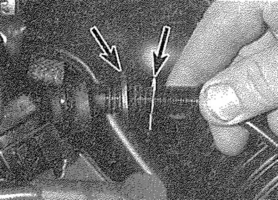
14.22. Free the accelerator cable from its mounting bracket and recover the washer and spring clip (arrowed)
23. Disconnect the element wiring connector, then undo the retaining screw and free the wiring connector from the throttle housing (see illustration).
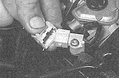
14.23. Disconnect the wiring connector, then undo the retaining screw and free the connector from its mounting bracket
24. Undo the four screws securing the accelerator cable bracket to the side of the throttle housing (see illustration). Carefully remove the bracket and recover the spring from the top of the heating element.
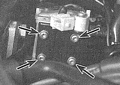
14.24. Accelerator cable bracket is retained by four screws (arrowed)
25. Ease the heating element out from the throttle housing. Examine the O-ring for signs of damage or deterioration and renew if necessary.
26. Refitting is a reversal of the removal procedure; where necessary, use a new O-ring.
Vehicle speed sensor
27. The vehicle speed sensor is an integral part of the speedometer drive housing. Refer to Chapter 7A or 7B for removal and refitting details.