



Table of contents: Fuel rail and injectors 🠇 Fuel pressure regulator 🠇 Throttle potentiometer 🠇 Electronic control unit (ECU) 🠇 Idle speed mixture adjustment…🠇 Idle speed auxiliary air valve 🠇 Idle speed stepper motor 🠇 Manifold absolute pressure (MAP)…🠇 Coolant temperature sensor 🠇 Inlet air temperature sensor 🠇 Crankshaft sensor 🠇 Knock sensor 🠇 Camshaft position sensor 🠇 Body accelerometer 🠇 Fuel injection system relay unit 🠇 Vehicle speed sensor 🠇 Throttle housing heating element 🠇
Fuel rail and injectors
Note 1: Refer to the warning note in Section 1 before proceeding.
Note 2: If a faulty injector is suspected, before condemning the injector, it is worth trying the effect of one of the proprietary injectorcleaning treatments which are available from car accessory shops.
1. Disconnect the battery negative terminal (refer to "Disconnecting the battery").
2. Remove the air cleaner assembly as described in Section 2.
3. On later models with the ignition HT coil module mounted above the fuel rail, remove the coil module as described in Chapter 5B.
4. On early models, disconnect the vacuum pipe from the fuel pressure regulator. On early 1587 cc models, undo the retaining nut and bolt and release the wiring/hose support clip from the end of the fuel rail.
5. Bearing in mind the information given in Section 7, disconnect the fuel feed and, on early models, the return hoses by slackening the retaining clips or disconnecting the quickrelease fittings (see illustration).
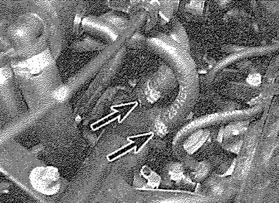
13.5. Release the clips (arrowed) and detach the fuel feed and return hoses from the fuel rail - early 1587 cc models
6. Disconnect the accelerator cable from the throttle cam and release the outer cable from the mounting bracket. Undo the bolts and remove the accelerator cable mounting bracket from the manifold/cylinder head.
7. Depress the retaining tangs and disconnect the wiring connectors from the four injectors. Slacken and remove the fuel rail retaining bolts and nuts, then carefully ease the fuel rail and injector assembly out from the inlet manifold and remove it from the engine. Remove the O-rings from the end of each injector and discard them; they must be renewed whenever they are disturbed.
8. Slide out the retaining clip and remove the relevant injector from the fuel rail (see illustration). Remove the upper O-ring from each disturbed injector and discard; all disturbed O-rings must be renewed.
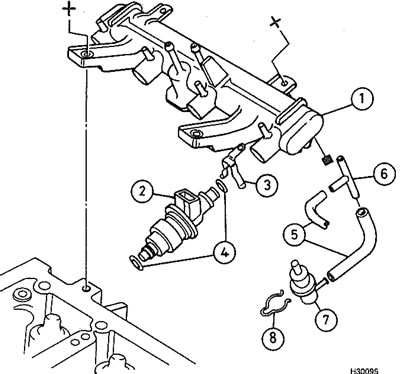
13.8. Fuel rail and injector components - early 1587 cc models 1. Fuel rail; 2. Injector; 3. Retaining clip; 4. O-ring seals; 5. Fuel hoses; 6. T-piece; 7. Fuel pressure regulator; 8. Retaining clip
9. Refitting is a reversal of the removal procedure, noting the following points.
- a) Fit new O-rings to all disturbed injector unions.
- b) Apply a smear of engine oil to the O-rings to aid installation, then ease the injectors and fuel rail into position ensuring that none of the O-rings are displaced.
- c) On later models, refit the ignition coil module as described in Chapter 5B.
- d) On completion, start the engine and check for fuel leaks.
Fuel pressure regulator
Note 1: The following procedure applies to models with the fuel pressure regulator mounted on the fuel rail. On later models, the regulator is an integral part of the fuel pump assembly and is not available separately.
Note 2: Refer to the warning note in Section 1 before proceeding.
10. Disconnect the battery negative terminal (refer to "Disconnecting the battery").
11. Disconnect the vacuum pipe from the reguiator. Note that on early models, access to the regulator is poor with the fuel rail in position, if necessary, remove the fuel rail as described earlier, then remove the regulator.
12. Bearing in mind the information given in Section 7, place a wad of rag over the regulator, to catch any fuel spray which may be released, then remove the retaining clip and ease the regulator out from the fuel rail.
13. Refitting is a reversal of the removal procedure. Examine the regulator seal for signs of damage or deterioration and renew if necessary.
Throttle potentiometer
14. Disconnect the battery negative terminal (refer to "Disconnecting the battery").
15. Depress the retaining clip and disconnect the wiring connector from the throttle potentiometer (see illustration).
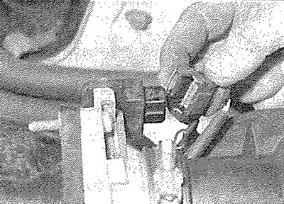
13.15. Disconnecting the throttle potentiometer wiring connector - 1587 cc models
16. Slacken and remove the two retaining screws, then disengage the potentiometer from the throttle valve spindle and remove it from the engine.
17. Refit in the reverse order of removal. Ensure that the potentiometer is correctly engaged with the throttle valve spindle.
Electronic control unit (ECU)
18. The ECU is located on the right-hand side of the engine compartment, underneath a large plastic cover. To remove it, first disconnect the battery negative terminal (refer to "Disconnecting the battery").
19. Unclip the cover from the mounting plate, then lift the retaining clip and disconnect the wiring connector from the ECU. Slacken and remove the ECU retaining bolts and remove it from the vehicle. Where applicable, disconnect the vacuum hose.
20. Refitting is a reverse of the removal procedure, ensuring that the wiring connector is securely reconnected.
Idle speed mixture adjustment potentiometer - 1360 cc (K6B engine) models
21. The idle speed mixture adjustment potentiometer is situated on the right-hand side of the engine compartment, on the underside of the ECU bracket. To remove it, first disconnect the battery negative terminal (refer to "Disconnecting the battery").
[Data published on the website PeugeotBook]
22. Depress the retaining tangs and disconnect the wiring connector, then undo the retaining screw and remove the potentiometer from the vehicle.
23. Refitting is the reverse of removal. On completion check and, if necessary, adjust the idle mixture setting (exhaust gas CO level) as described in Chapter 1A.
Idle speed auxiliary air valve
24. The auxiliary air valve is only fitted to 1587 cc models with Bosch Motronic MP5.1 and MP5.2 systems. The valve is mounted on the underside of the inlet manifold (early models) or on the right-hand end of the inlet manifold casting (later models). On all other models, idle speed regulation is via a stepper motor as described in the next sub-Section.
25. Disconnect the battery negative terminal (refer to "Disconnecting the battery").
26. Depress the retaining clip and disconnect the wiring connector.
27. Slacken the retaining clips and disconnect the air hose from the end of the auxiliary air valve.
28. On early models, slide the valve out from its mounting bracket, and remove it from the engine compartment. On later models, undo the securing screw and withdraw the valve from the manifold (see illustration).
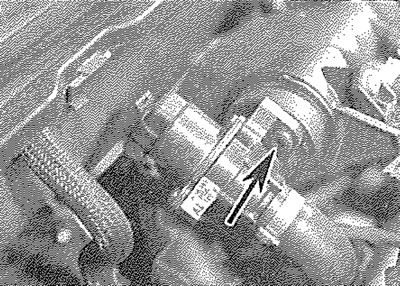
13.28. Idle speed auxiliary air valve securing screw (arrowed) - later 1587 cc models
29. Refitting is a reversal of the removal procedure. Examine the mounting rubber for signs of deterioration and renew it if necessary.
Idle speed stepper motor
30. The idle speed stepper motor is located on the side of the throttle housing assembly.
31. Disconnect the battery negative terminal (refer to "Disconnecting the battery").
32. Release the retaining clip and disconnect the wiring connector from the motor (see illustration).
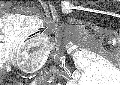
13.32. Disconnect the wiring connector from the idle speed stepper motor (arrowed)...
33. Slacken and remove the two retaining screws, and withdraw the motor from the throttle housing (see illustration).
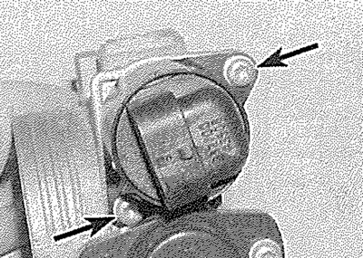
13.33. ... then undo the retaining screws (arrowed) and remove the motor from the throttle housing - 1360 cc models
34. Refitting is a reversal of the removal procedure.
Manifold absolute pressure (MAP) sensor
Note: On 1360 cc models with Bosch Motronic MP3.1, the MAP sensor is an integral part of the system electronic control unit and cannot be separately removed.
35. On early 1587 cc models, the pressure sensor is situated remotely on the right-hand side of the engine compartment bulkhead. On ail other models, the sensor is mounted directly on the front of, or on the right-hand side of, the inlet manifold.
36. Disconnect the battery negative terminal (refer to "Disconnecting the battery").
37. On early 1587 cc models, undo the retaining nut, and free the sensor from its mounting bracket. Disconnect the wiring connector and vacuum hose and remove the sensor from the engine compartment.
38. On all other models, remove the securing screw and with withdraw the sensor from the manifold (see illustration). Disconnect the wiring connector, and remove the sensor from the engine.

13.38. Manifold pressure sensor securing screw (arrowed) - later 1587 cc models
39. Refitting is the reverse of the removal procedure.
Coolant temperature sensor
40. Refer to Chapter 3.
Inlet air temperature sensor
41. On early models, the inlet air temperature sensor is screwed into the air cleaner housing lid. On later models it is located on the underside of the throttle housing.
42. Disconnect the battery negative terminal (refer to "Disconnecting the battery").
43. Disconnect the wiring connector, then unscrew the sensor, or release the retaining clips and remove it from the vehicle.
44. Refitting is the reverse of removal.
Crankshaft sensor
45. The crankshaft sensor is situated on the front face of the transmission clutch housing.
46. Disconnect the battery negative terminal (refer to "Disconnecting the battery").
47. Trace the wiring back from the sensor to the wiring connector and disconnect it from the main harness.
48. Prise out the rubber grommet, then undo the retaining bolt and withdraw the sensor from the transmission unit.
49. Refitting is reverse of the removal procedure ensuring the sensor retaining bolt is securely tightened and the grommet is correctly seated in the transmission housing.
Knock sensor
50. The knock sensor is screwed onto the rear face of the cylinder block.
51. Disconnect the battery negative terminal (refer to "Disconnecting the battery").
52. To gain access to the sensor, chock the rear wheels then jack up the front of the vehicle and support it on axle stands (see "Jacking and vehicle support").
53. Trace the wiring back from the sensor to its wiring connector, and disconnect it from the main loom.
54. Slacken and remove the bolt securing the sensor to the cylinder block, and remove it from underneath the vehicle.
55. Refitting is a reversal of the removal procedure, ensuring that the sensor wiring is correctly routed and its retaining bolt is tightened securely.
Camshaft position sensor
Note: Later engines with secondary air injection.
56. The camshaft position sensor is fitted to the rear of the coolant outlet housing on the left-hand end of the cylinder head. To remove It, first disconnect the battery negative terminal (refer to "Disconnecting the battery").
57. Disconnect the wiring connector then unscrew the retaining bolt and remove the sensor from the housing.
58. Refitting is the reverse of removal ensuring the sensor seal is in good condition.
Body accelerometer
Note: Later engines with secondary air injection.
59. The body accelerometer is located in the engine compartment. To remove it, first disconnect the battery negative terminal (refer to "Disconnecting the battery").
60. Disconnect the wiring connector then unscrew the mounting bolt and remove the sensor from the vehicle.
61. Refitting is the reverse of removal.
Fuel injection system relay unit
62. The relay unit is clipped onto the underside of the ECU mounting plate, on the right-hand side of the engine compartment.
63. To remove the relay unit, first disconnect the battery negative lead (refer to "Disconnecting the battery").
64. Unclip the relay unit from the mounting plate, disconnect the wiring connector and remove the unit from the vehicle.
65. Refitting is the reverse of removal, ensuring that the relay unit is securely held in position by its retaining clip.
Vehicle speed sensor
66. The vehicle speed sensor is an integral part of the speedometer drive housing. Refer to Chapter 7A or 7B, as applicable, for removal and refitting details.
Throttle housing heating element
Note: The heating element is only fitted to aluminium throttle housings. Plastic housings do not need a heater.
67. The heating element is fitted to the top of the throttle housing.
68. Disconnect the wiring connector then unscrew the retaining screw and remove the heating element from the throttle housing.
69. Refitting is the reverse of removal.