



Removal
Models with a distributor
1. Disconnect the battery negative terminal (refer to "Disconnecting the battery").
2. Disconnect the hot-air intake hose from the exhaust manifold shroud and air temperature control valve and remove it from the engine. Release the intake duct fastener and position the duct clear of the coil.
3. Disconnect the wiring connector from the capacitor mounted on the coil mounting bracket and release the TDC sensor wiring connector from the front of the bracket (see illustration).
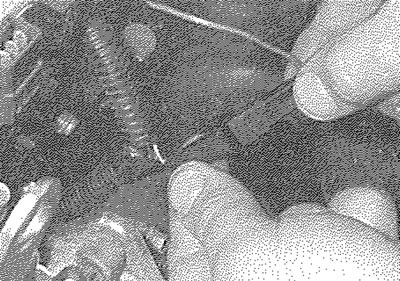
3.3. On models with a distributor, disconnect the capacitor wiring connector and release the TDC sensor connector...
4. Disconnect the HT lead from the coil, then depress the retaining clip and disconnect the coil wiring connector (see illustrations).
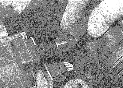
3.4a.... then disconnect the HT lead...
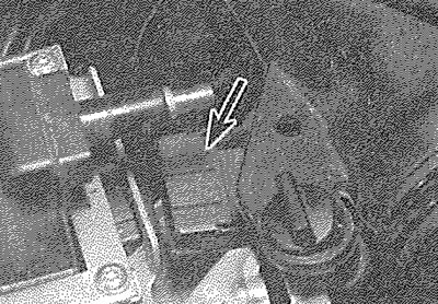
3.4b.... and wiring connector (arrowed) from the ignition HT coil
5. Slacken and remove the two retaining bolts and remove the coil and mounting bracket from the cylinder head. Where necessary, slacken and remove the four screws and nuts and separate the HT coil and mounting bracket (see illustrations).
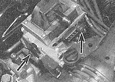
3.5a. Undo the two retaining bolts (arrowed)...
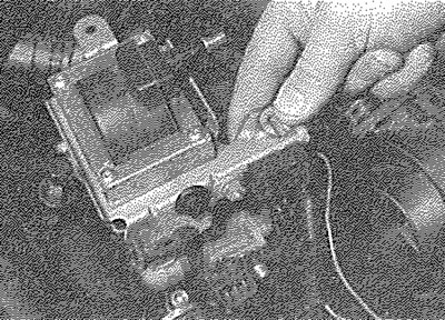
3.5b.... and remove the coil and mounting bracket from the engine
8-valve models with cylinder head mounted ignition coil
6. The ignition HT coil is mounted on the lefthand end of the cylinder head.
7. Disconnect the battery negative terminal (refer to "Disconnecting the battery"), then depress the retaining clip and disconnect the wiring connector from the HT coil (see illustration).
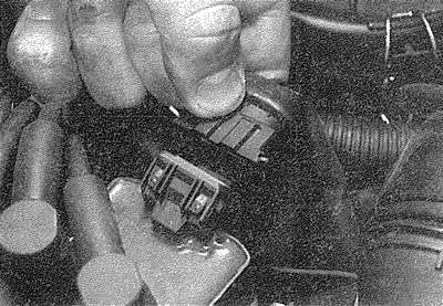
3.7. On models with a cylinder head mounted ignition coil, disconnect the coil wiring connector...
8. Make a note of the correct fitted positions of the HT leads then disconnect them from the coil terminals (see illustration 3.9).
9. Undo the four retaining screws securing the coil to its mounting bracket and remove it from the engine compartment (see illustration).
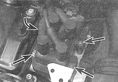
3.9. ... then disconnect the HT leads from the coil. Undo the four screws (arrowed) and remove the coil
8-valve models with spark plug mounted ignition coil module
10. Disconnect the battery negative terminal (refer to "Disconnecting the battery").
11. Disconnect the engine breather hose at the quick-release connections on the air cleaner air inlet duct, cylinder head cover and inlet manifold. Move the hose to one side.
12. Unplug the wiring connector from the top of the ignition coil unit (see illustration).
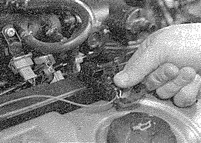
3.12. Unplug the wiring connector from the top of the ignition coil unit
13. Where applicable, unscrew the securing nut and remove radio suppresser from the right-hand end of the coil unit, together with its mounting bracket (see illustrations).
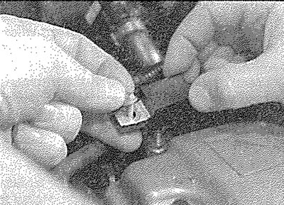
3.13a. Remove radio suppresser from the right-hand end of the coil unit...
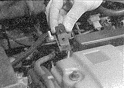
3.13b.... together with its mounting bracket
14. Undo the nut securing each end of the ignition coil unit to the mounting studs (see illustration). Note that it is quite likely that the stud will be released with the nut.
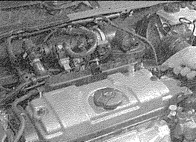
3.14. Remove the securing nuts...
15. Lift the ignition coil unit upwards off the mounting studs and at the same time carefully ease the HT extension pillars away from the tops of the spark plugs. Lift the unit off the plugs and withdraw it from the engine (see illustration).
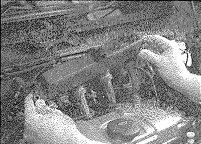
3.15. ... and lift the ignition coil unit from the mounting studs
16-valve models
16. Disconnect the battery negative terminal (refer to "Disconnecting the battery").
17. Remove the securing screws and lift the trim panel away from the top of the ignition coil unit, located between the cylinder head covers. Disconnect the wiring connectors from the left-hand end of the coil module.
18. Slacken and withdraw the ignition coil module securing screws, then lift the module away from the cylinder head. Remove the HT extension pillars if they remain connected to the tops of the spark plugs.
Testing
8-valve models
19. Testing of the coil is carried out using a multi-meter set to its resistance function, to check the primary (LT to terminals) and secondary (LT "+" to HT lead terminal) windings for continuity. Bear in mind that on the four-output, static type HT coil, there are two sets of each windings. Compare the results obtained to those given in the Specifications at the start of this Chapter. The resistance of the coil windings will vary slightly according to the coil temperature - the results in the Specifications are approximate values for when the coil is at 20°C.
20. Check that there is no continuity between the HT lead terminal and the coil body/mounting bracket.
21. If the coil is thought to be faulty, have your findings confirmed by a Peugeot dealer before renewing the coil.
16-vaIve models
22. The circuitry arrangement of the ignition coils and the coil unit on these engines is such that testing of an individual coil in isolation from the remainder of the engine management system is unlikely to prove effective in diagnosing a particular fault. Should there be any reason to suspect a faulty individual coil, the engine management system should be tested by a Peugeot dealer using diagnostic test equipment (see Section 2).
Refitting
23. Refitting is a reversal of the relevant removal procedure. Ensure that the wiring connectors and the HT lead are securely reconnected.