



The electronic control unit for the ignition and fuel injection systems contains so-called parametric characteristics obtained during bench tests. In addition, the ignition system control unit receives information from the following system components:
- flywheel sensor. These are signals about the engine speed and the position of the crankshaft.
- coolant temperature and intake air temperature sensors.
- throttle position potentiometer. Information from this potentiometer is received both at the moment of engine start and when the engine is idling.
Based on the information received from these sensors, the electronic control unit calculates the ignition advance angle, sets the ignition coil charging duration in accordance with the engine speed, determines the battery voltage and the voltage on both coil windings.
The ignition timing angle is changed by the control unit based on the parametric characteristics stored in its memory. If the engine is operated under extreme conditions, the ignition timing can be adjusted in the workshop to suit these operating conditions by resetting (deleting) the programmed characteristics. This adjustment protects the engine from possible engine damage caused by detonation combustion of fuel as a result of refueling with low-octane gasoline or low-quality gasoline. If such a situation can be predicted in advance, for example, when traveling to a country where the fuel quality leaves much to be desired, then it is recommended to contact a workshop to make the appropriate adjustments to the ignition system control unit memory.
The ignition timing is adjusted in 2° increments. The maximum ignition timing adjustment is 8°. This adjustment requires control and measuring instruments available only in workshops.
The ignition system components are shown in Figure 2.0.
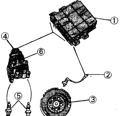
2.0 Elements of the ignition system.
1 - electronic control unit
2 - engine speed sensor
3 - flywheel with two missing teeth for determining the position of the crankshaft
4 - ignition coil
5 - spark plugs
6 - the second output stage of the ignition coil
The two spark plugs shown in this illustration are connected to the second output stage of the ignition coil. The diagram shown is typical, but on some engines the position of the spark plugs may be different.
To remove the ignition coil, you need to disconnect the battery and also disconnect the plug. After this, it is necessary to disconnect the high-voltage wires from the spark plugs and unscrew the four bolts securing the ignition coil. The procedure for installing the coil back in place is the opposite of removal.
Ignition timing angle
The ignition timing angle cannot be adjusted. Checking and entering basic parametric characteristics is only possible using control and measuring instruments and must be performed by the workshop.
Defective ignition system components can cause engine malfunctions. If the engine is running poorly, the cause may be a faulty engine speed sensor, crankshaft position sensor, ignition coil, or control unit.
If the engine does not work at all, but the main functions of the ignition system are in order, then the cause of engine failure may be a malfunction of the automatic ignition timing adjustment. Only a workshop can identify and fix such a failure, as it requires control and measuring instruments to create a corresponding diagram that allows for quick detection of the error in the settings.