
Removing
To remove the smart junction box:
- disconnect the wire «masses» from the storage battery;
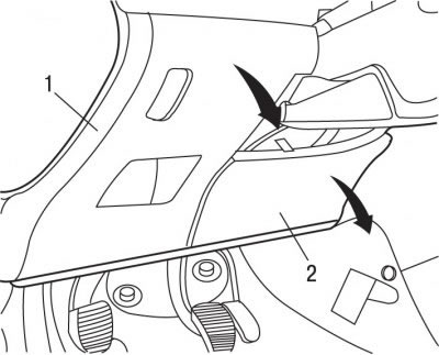
Pic. 9.5. Fuse box location: 1 - cover; 2 - finishing panel
- to access the intelligent switching unit located in the instrument panel, remove the cover 1 (see fig. 9.5), releasing it from the latches and pulling down;
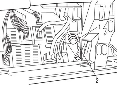
Pic. 9.8. Lock Location (1) and staples (2) fastening of the intelligent switching unit
- on each side of the smart junction box, release the latches 1 (pic. 9.8), turning them a quarter of a turn, remove the lower brackets 2 of the fasteners and tilt the unit away from the instrument panel;
- disconnect all electrical connectors from the intelligent junction box;
- slightly lift the back of the smart junction box and pull it towards you to remove it from its support;
- remove the intelligent junction box.
Installation
To install an intelligent junction box:
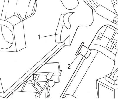
Pic. 9.9. Installation of an intelligent switching unit: 1 - support brackets for the recess of the instrument panel; 2 - guide rods
- install the intelligent switching unit on the support by inserting the guide rods 2 (pic. 9.9) into the support grooves of the bracket 1 of the instrument panel;
- connect all electrical connectors to the intelligent junction box;
- further installation is carried out in the reverse order of removal;
- in case of replacement of the intelligent switching unit with the help of the DIAG 2000 device, adapt its configuration;
- connect wire «masses» to the battery;
- check the functionality of the unit;
- initiate all electronic systems.