
English Русский
Български
Беларускі
Український
Српски
Hrvatski
Română
Polski
Slovenský
Magyar
Bookmark Articles Sitemap Contacts
Company Hyundai Company Opel Company Skoda Company Kia Company Mitsubishi Company LADA Company Audi
PeugeotBook.ru


Series 100   Series 200   Series 300   400-500   Series 600   Crossovers   Others
 
Peugeot 305 (1977-1989) Peugeot 306 (1993-2002) Peugeot 307 (2001-2008)

Replacing the COM 2000 steering column switch unit (Peugeot 307)

  • Main
  • 30X
  • Peugeot 307 (2001-2008)
  • Electrical equipment
  • Equipment and devices
  • Replacing the COM 2000 steering column switch unit
0
To remove the COM 2000 steering column switch unit:
  • set the front wheels to move straight ahead;
  • disconnect the ground wire from the battery;
  • remove the driver's side airbag;
  • loosen the steering wheel mounting bolt a few turns;
  • slide the steering wheel off the splines, if necessary, hitting it with your hands from the back along its perimeter;
  • unscrew the steering wheel mounting bolt;
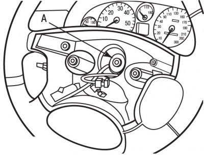
Figure 7.2. Location of alignment marks (A) on the steering wheel and the end of the steering shaft

Figure 7.2. Location of alignment marks (A) on the steering wheel and the end of the steering shaft

  • apply marks A with chalk, marker or paint (see Figure 7.2) alignment on the steering wheel and the end of the steering shaft. Marks are necessary to reinstall the steering wheel to its original position;
  • disconnect the electrical connectors from the steering wheel;
  • remove the steering wheel, first passing the electrical connectors one by one through the cutouts in the steering wheel;
  • remove the steering column cover mounting screws located under the lower cover;
  • remove the lower steering column cover;
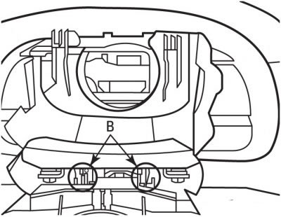
Figure 7.3. Location of the fasteners (B) of the upper steering column cover

Figure 7.3. Location of the fasteners (B) of the upper steering column cover


  • release from clamps B (see Figure 7.3) upper steering column cover and remove it;
  • disconnect the electrical connectors from the COM 2000 steering column switch unit;
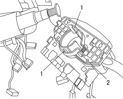
Figure 9.25. Location of the clamps (1) and bolt (2) for securing the COM 2000 steering column…

Figure 9.25. Location of the clamps (1) and bolt (2) for securing the COM 2000 steering column switch unit clamp

  • unscrew bolt 2 (figure 9.25) fastening the clamp of the steering column switch unit;
  • release the COM 2000 steering column switch unit by pressing the fasteners 1 and remove it.

Sequence of actions when adjusting the position of the contact ring:

1) For the EATON type COM 2000 switch block, do the following:
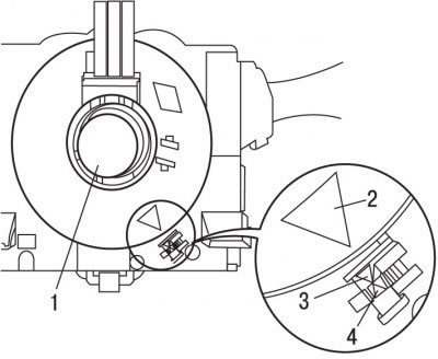
Figure 9.26. Adjusting the position of the slip ring: 1 - contact ring of the COM 2000 switch block…

Figure 9.26. Adjusting the position of the slip ring: 1 - contact ring of the COM 2000 switch block type EATON; 2, 3, 4 - installation triangles


  • press the central part of the contact ring 1 and turn it until the mounting triangles 2, 3 and 4 align (figure 9.26);

Note: The new contact ring of the COM 2000 steering column switch unit does not require additional adjustments.


2) For the COM 2000 switch block of the SYLEA type, do the following:
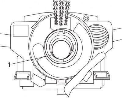
Figure 9.27. Contact ring (1) of the COM 2000 switch block of the SYLEA type

Figure 9.27. Contact ring (1) of the COM 2000 switch block of the SYLEA type

  • press the central part of the contact ring 1 (figure 9.27) and turn it in any direction until it stops;
  • while continuing to press, turn it all the way in the opposite direction and count the number of turns (about 5 turns);
  • rotate the contact ring to its middle position (about 2.5 turns).

Note: The airbag wire harnesses must be facing up.


Installation is carried out in the reverse order of removal, taking into account the following:
  • connect the ground wire to the battery;
  • check the functionality of the COM 2000 steering column switch unit;
  • initiate all electronic systems.
This article is available at russian, bulgarian, belarusian, ukrainian, serbian, croatian, romanian, polish, slovak, hungarian
Article reviewed by editor: Sidorov Timofey
Share information:
Previous
Peugeot 307: Equipment and devices
Next

Replacing the instrument cluster
Replacing exterior lighting bulbs
Replacing the license plate light
Replacing the high brake light
Replacing the rear light
Replacing the ignition switch
Replacing the multifunction display
Replacing the light brightness sensor
Replacing the windshield wiper
Replacing the wiper blade
See similar information for other Peugeot models

➨ Ignition switch/ steering column lock — removal and refitting Peugeot 106 (1991-2003)
➨ Steering column switch Peugeot 207 (2006-2014)
➨ Replacing the steering gear protective covers Peugeot 405 (1987-1997)
➨ Steering column switch block — removal and installation Peugeot 605 (1989-2000)
➨ Ignition switch and steering column lock, horn switch Peugeot Partner I (1996-2008)
Link to this article in different formats
Comments and feedback from visitors
No comments yet


Add two numbers 10 + 47


Peugeot 307 (2001-2008) 
  • User manual
  • Keys, doors and alarm
  • Controls and instruments
  • Driving and operation
  • Maintenance
  • Power unit
  • Petrol engines TU3 and TU5
  • Petrol engines EW10
  • Diesel engines DV10
  • Diesel engines DW10
  • Transmission
  • Clutch and drive shafts
  • Mechanical gearbox
  • Automatic gearbox
  • Chassis, running gear
  • Front suspension
  • Rear suspension
  • Steering
  • Brake system
  • Body and interior
  • Exterior (external elements)
  • Interior (internal elements)
  • Doors, locks and windows
  • Heating and air conditioning
  • Electrical equipment
  • Equipment and devices
  • Power devices
  • Airbags
  • Electrical circuits
Peugeot 306 (1993-2002) 
  • General information
  • Introduction to manual
  • Specifications
  • Gasoline engine
  • Engine repair
  • Lubrication system
  • Cooling system
  • Fuel injection
  • Ignition system
  • Diesel engine
  • Engine repair
  • Lubrication system
  • Cooling system
  • Fuel injection
  • Transmission
  • Clutch
  • Gearbox
  • Drive shafts
  • Chassis, running gear
  • Steering system
  • Front suspension
  • Rear suspension
  • Brake system
  • Electrical equipment
  • Power devices
  • Electrical circuits
Peugeot 305 (1977-1989) 
  • General information
  • Maintenance
  • Power unit
  • Gasoline engines
  • Diesel engines
  • Cooling system (gasoline)
  • Cooling system (diesel)
  • Fuel system (gasoline)
  • Fuel system (diesel)
  • Ignition system
  • Transmission
  • Clutch
  • Mechanical gearbox BB8
  • Mechanical gearbox BE1
  • Automatic gearbox ZF4
  • Shafts, hubs and wheels
  • Chassis, running gear
  • Brake system
  • Car suspension
  • Steering
  • Body and interior
  • Exterior (external elements)
  • Interior (internal elements)
  • Electrical equipment
  • Equipment and devices
  • Headlights and lighting
  • Power devices
  • Electrical circuits
  • Wiring diagrams (diesel)
PeugeotBook.ru © 2018–2026 | Mobile version | Sitemap: EN BG BY UA RS HR RO PL SK HU | Write message | Site search | Add to bookmarks | Peugeot owners
106 (1991-2003) | 206 (1998-2012) | 207 (2006-2014) | 305 (1977-1989) | 306 (1993-2002) | 307 (2001-2008) | 405 (1987-1997) | 406 (1995-2004) | 605 (1989-2000) | Partner-I (1996-2008) | Eurovans-807 (2002-2014) | Eurovans-806 (1994-2002) | J5 (1981-1993) |
Cookies are used to ensure the correct display of pages on the site.