



- disconnect the ground wire from the battery;
Important! Before removing the wiper blades, start the engine, then, with the ignition off, press down on the windshield wiper lever to move the mechanism to the "Sell" position. Pressing the lever again will move the wiper blades to the "Stop" position.
- remove the wiper arms;
- unscrew the two bolts securing the brake fluid expansion tank, move the tank to the side and secure it in this position;
- remove the decorative engine cover;
- remove the air filter housing;
- remove the cover from the electrical fuse box;
- remove the cover from the battery;
- remove the battery;
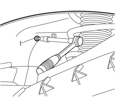
Figure 5.20. Unscrewing the bolt (1) securing the battery support
- on vehicles with DW10ATED engines, remove the decorative cover of the windshield washer reservoir. Remove the left front wheel arch mudguard. Remove bolt 1 from under the left front wheel arch (see Figure 5.20) battery support mounts and remove it;
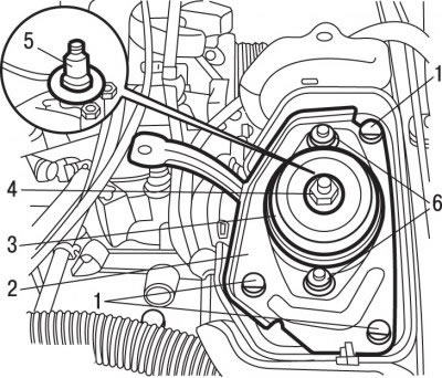
Figure 5.13. Fastening the elastic support: 1 - bolts; 2 - bracket; 3 - elastic support; 4 - nut, 65 Nm; 5 - gearbox axis; 6 - bolts, 30 Nm
- unscrew nut 4 (see Figure 5.13) fasteners from the gearbox support axle and remove it together with the washer;
- lower the engine and transmission assembly to make it easier to remove the windshield wiper;
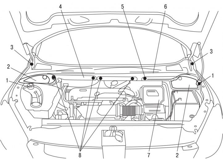
Figure 9.32. Panel grille in front of the windshield: 1 - bolts; 2 - side soundproofing coverings; 3 - clamps; 4 - soundproofing coating; 5 - crossbar; 6 - grille; 7 - battery support; 8 - clamps
- remove the clamps 8 (figure 9.32) fastenings of soundproofing coating;
- remove the sound-insulating covering 4 by releasing it from the clips on the access hatch to the particulate filter;
- remove the side soundproofing coverings 2;
- unscrew bolts 1 and remove crossbar 5 from the lower part of the windshield opening;
- remove the 3 fasteners securing the grille of the panel in front of the windshield;
- remove the 6 panel grille in front of the windshield;
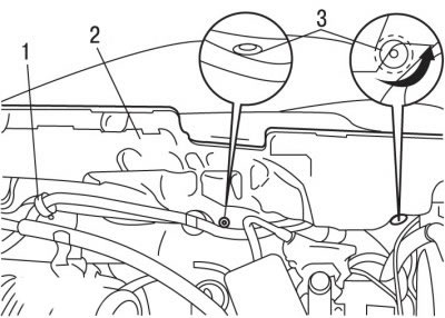
Figure 9.33. Location of fasteners: 1 - wiring harness mounting bracket; 2 - fastening of soundproofing covering; 3 - clamps
- release bracket 1 from the clamps (figure 9.33) wiring harness fasteners;
- remove the fasteners 3 by unscrewing them by hand;
- remove the soundproofing coating 2;
- remove the windshield wiper motor;
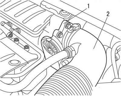
Figure 9.34. Location of the air intake pipe (2) and throttle assembly (1) on vehicles with TU5JP4 engines
- on vehicles with TU5JP4 engines, remove the air intake pipe 2 (figure 9.34);
- unscrew the throttle assembly mounting bolts 1, move it to the side and secure it in this position;
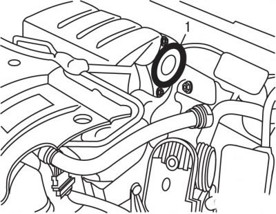
Figure 9.35. Location of the sealing ring (1) from the intake manifold on vehicles with TU5JP4 engines
- remove sealing ring 1 (figure 9.35) from the intake manifold;
- cover the intake manifold opening with tape;
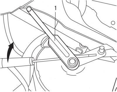
Figure 9.36. Releasing the rod (1) from the retainer using a screwdriver
- release rod 1 (figure 9.36) from the retainer using a screwdriver;
- protect the upper supports of the front support elements with adhesive tape;
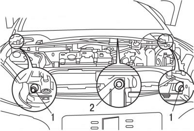
Figure 9.37. Location of bolts (1) and nuts (2) for securing the windshield wiper
- unscrew bolts 1 of the side fasteners and nut 2 (figure 9.37) central windshield wiper mount;
- disconnect the electrical connector from the windshield wiper mechanism;
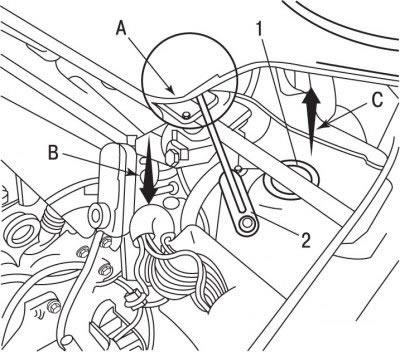
Figure 9.38. Preliminary removal of the left side of the windshield wiper mechanism: 1 - upper part of the left shock absorber; 2 - thrust; A - lower part of the windshield; B - direction of pressing the front part of the windshield wiper mechanism; C - direction of pressing the rear part of the windshield wiper mechanism
Source of the article is posted at (www.PeugeotBook.ru)
- remove the windshield wiper mechanism from the guide rods;
Caution: When removing the windshield wiper mechanism, be careful not to allow contact between the windshield and rod 2 in area A (figure 9.38).
- press the front part of the wiper mechanism at point B and lift the rear part at C to pass the left side of the wiper mechanism over the mount 1 of the left shock absorber;
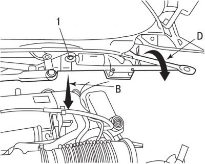
Figure 9.39. Removing the left side of the windshield wiper mechanism: 1 - windshield wiper mechanism; B - direction of pressing the front part of the windshield wiper mechanism; D - direction of removal of the rear part of the windshield wiper mechanism
- press the front of the wiper mechanism again at point B (figure 9.39) and tilt the mechanism forward D to pass the upper part of the mechanism 1 under the windshield;
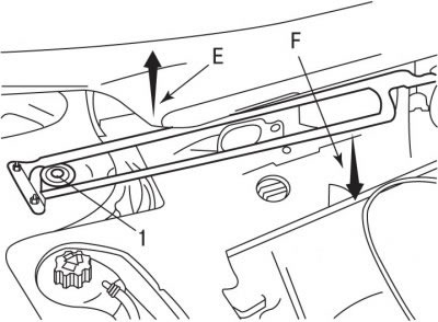
Figure 9.40. Preliminary removal of the right side of the windshield wiper mechanism: 1 - upper part of the right shock absorber; E - direction of pressing the front part of the windshield wiper mechanism; F - direction of pressing the rear part of the windshield wiper mechanism
- press the front of the windshield wiper mechanism at point E (figure 9.40) and lift the rear section at point F to pass the right side of the windshield wiper mechanism over the mount 1 of the right shock absorber;
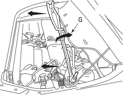
Figure 9.41. Direction of rotation of the windshield wiper mechanism (G) before removal from the vehicle
- turn the windshield wiper mechanism in accordance with arrow G shown in the figure 9.41, move it forward and remove it from the car.
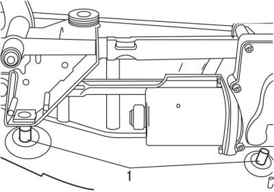
Figure 9.42. Location of centering rods (1) of the windshield wiper mechanism
Installation is carried out in the reverse order of removal, taking into account the following:
Attention! When installing, make sure that the two centering rods 1 (figure 9.42), located behind the gear motor, fell into place (otherwise, the mechanism will be installed in such a way that it may fail to operate, and it may also be moved to the point of contact with the windshield). You can only make sure that the centering rods are in their sockets by touch.
- tighten bolts 1 (see Figure 9.37) and nut 2 securing the windshield wiper mechanism with a torque of 10 N·m;
- press down on the wiper arm to set the wiper mechanism to the "Fixed Stop" position;
- install the wiper arms and blades back into place;
- connect the ground wire to the battery;
- check the operation of the windshield wiper;
- initiate all electronic systems.