
The MM 8P system is a multipoint fuel injection system where all injectors inject fuel simultaneously - i.e. at a time and twice per engine cycle.
Fuel burner
Fuel burner (see illustration 12.21 or 12.22) has electromagnetic control. The electronic control unit drives the injectors. The voltage to the injectors comes from the main relay. The duration of the nozzle opening is between 1.5 and 10 milliseconds. The duration of fuel injection depends on engine temperature, engine load, engine speed and operating conditions.
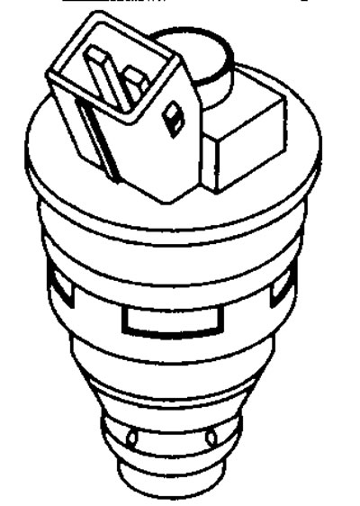
12.21 Fuel injector (XU7JP)
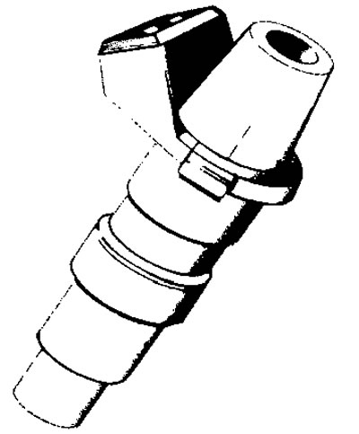
12.22 Fuel injector (XU10J2C)
When the solenoid valve closes, a reverse electromagnetic field voltage of up to 60 volts is generated.
Since the injectors inject fuel at the same time, the fuel is briefly returned back to the valve before entering the cylinder.
When starting the engine, the injectors inject fuel twice per engine cycle.
Nozzle voltage values
Terminal numbers

See illustration 12.23
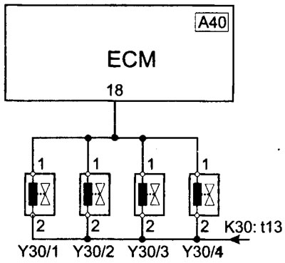
12.23 Fuel injector wiring diagram
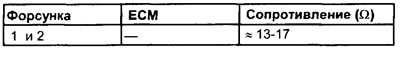
Nozzle resistance values
Note. The voltage is supplied by the fuel injection relay and is only available for approximately one second after the ignition is turned on - either when cranking or with the engine running. Bypassing the relay provides the voltage required for testing.
Terminal numbers
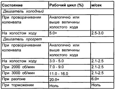
Nozzle Duty Cycle Table
Frequency
When starting the engine: twice per revolution.
Engine running: once per revolution.
Nozzle type
Multipoint fuel injection.
Influence of external factors
- Vacuum leaks
- Ignition system malfunction
- Air filter clogged
- Engine oil contaminated
- Fuel Tank Ventilation Malfunction
Checking the injectors (general check)
1. Inspect the injector multi-pin connectors for signs of corrosion or damage.
2. Make sure the pins on the multi-pin connector are properly installed and making good contact with the injectors.
3. Check for corrosion at the relay and injector terminals, and at the ECU and injector terminals. Corrosion on the terminals is the cause of poor injector performance.
Checking the performance of the injector using an oscilloscope or a meter for the duration of the closed state of the breaker contacts
1. Two wires are routed to the injector multi-pin connector: a power wire and a signal wire.
2. Peel back the rubber insulation (where possible) to the multi-pin connector of the injector or connect the outlet block (WWII) between the multi-pin connector of the electronic control unit and the electronic control unit.
3. Connect the negative lead of an oscilloscope or breaker closed time meter to ground on the motor.
4. Connect the positive probe of an oscilloscope or a meter for the duration of the closed state of the breaker contacts to terminal No. 1 of the signal wire of the injector. Since the injectors inject fuel in pairs, one injector from each pair will be suitable for testing. Note. The injector signal will only be received on the wire connecting the injector to the ECU. If it is not possible to get a reading, then connect the probe to another terminal and repeat the test.
Checks with the engine off
1. Turn the crankshaft.
2. The instrument will display either a waveform or duty cycle reading. If the device can measure readings in milliseconds, then this is the most successful measurement (see illustration 12.24)
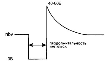
12.24 Typical input waveform to injectors
3. Clear waveform or sufficient signal. Key points to consider:
- Does the waveform match the pattern?
- Is the pulse signal length appropriate for the temperature?
4. If the answer to these two questions is «Yes», then the cause of the engine not starting is unlikely to be related to the fuel injection system. However, a fuel pressure test should be performed.
5. If the ignition coil primary signal is sufficient, then the fault is unlikely to be related to the electronic control unit.
Fuzzy or no waveform or no signal
1. Check for sufficient signal from the crankshaft angle sensor.
2. Check the voltage supply to the injector multi-pin connector.
3. If there is no voltage, check the resistance of the injector and the voltage supply to the injector.
Note. If the oscilloscope shows voltage at the nominal voltage of the battery, but there is no waveform, then voltage is supplied to the injector, but the circuit does not turn on.
4. Check the duration of opening of other nozzles
5. Disconnect the multi-pin connector of the electronic control unit (see warning #3).
6. Turn on the ignition.
7. Using the jumper wire, very quickly touch the injector pin in the ECU multi-pin connector to ground.
8. If the nozzle fires, then check the voltage supply to the electronic control unit and its grounding. If the voltage supply and grounding are in order, then the electronic control unit may be faulty.
8. If the nozzle fires, then check the voltage supply to the electronic control unit and its grounding. If the voltage supply and grounding are in order, then the electronic control unit may be faulty.
9. If the injector does not fire, check for battery voltage at the ECU pin.
10. If voltage is present, the injector may be defective.
11. If there is no voltage, check the continuity of the electrical wiring going between the multi-pin connectors of the injector and the multi-pin connector of the electronic control unit.
A Pulse duration that is too long or too short
1. Check the coolant temperature sensor (CTS).
2. Check the intake manifold absolute pressure sensor (IDA).
Note. If the ECM was using LOS mode due to one of the sensors failing, the engine may run properly while it is warm. However, it may be difficult to start the engine from a cold state.
Checks with the engine running
1. Run the engine at various speeds. Record the values obtained at the following engine speeds.
- idle speed
- At 2000 rpm
- At 3000 rpm
- When opening the throttle slowly
- When opening the throttle quickly
- When braking: increase the engine speed to approximately 3000 rpm and release the throttle.
2. Compare the results with the values specified in the specifications, both on a cold and warm running engine.
3. Pulse duration as a percentage (%) should increase as the engine speed increases.
4. The duration of the pulse in ms should not change significantly with a gradual increase in engine speed.
5. When accelerating, the pulse duration should increase.
6. When braking, when the engine is warm, the oscilloscope should not display the pulse width, or it should fall to zero (digital measuring instrument) and reappear when the engine speed is reduced.
7. If the value of the device does not drop to zero, then check the correct adjustment of the throttle valve and the performance of the throttle position sensor (TPS). The noise from the injectors should also temporarily disappear as the fuel cut-off valve will operate.
A Pulse duration that is too long or too short
1. Check the coolant temperature sensor (CTS).
2. Check the intake manifold absolute pressure sensor (IDA).
Note. If the ECM was using LOS mode due to one of the sensors failing, the engine may run properly while it is warm. However, it may be difficult to start the engine from a cold state.
Resistance Tests
Nozzle
Remove the injector multi-pin connectors and measure the injector resistance between the two terminals.
Injector circuit
1. Disconnect the fuel injection relay. All nozzles are connected.
2. Measure the resistance at the indicated terminals of the electronic control unit. The resistance of the injector circuit must match the values specified in the specifications.
3. If the resistance does not correspond to the nominal value, then this may be caused by:
- Injector failure.
- Wiring fault.
Fuel system
When the ignition is turned on, the ECM energizes the fuel pump relay for approximately one second, pressurizing the fuel system. The fuel pump relay then turns off. As soon as the engine starts, fuel is supplied through the non-return valve and fuel filter to the fuel line.
To prevent loss of pressure in the fuel supply system, a non-return valve is located in the outlet pipe of the fuel pump. When the ignition is turned off and the fuel pump stops working, the pressure is thus maintained for some time.
Fuel volume
From 2.0 to 2.4 liters per minute.
Fuel pressure
| State | State |
| Idle | 2.0 bar |
| Engine off | 2.5 bar |
| Maximum allowable pressure | Not specified |
Fuel pump
Fuel pump installed inside the fuel tank (Citroen)
Two stage fuel pump (see illustration 12.25) mounted horizontally on the bottom of the fuel tank.
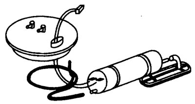
12.25 Fuel pump installed horizontally in the fuel tank
Fuel pump installed inside the fuel tank (Peugeot)
The fuel pump is mounted vertically in the fuel tank and includes an external and internal gear set.
Fuel pump voltage values
Note. The supply voltage is only available when the crankshaft is cranked or the engine is running. Starting the fuel pump when the ignition is on (engine off), needed to bypass the relay.
Terminal numbers
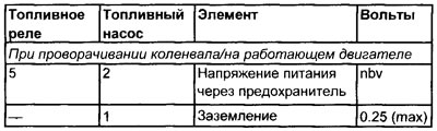
See illustration 12.2
Influence of external factors
- Damaged battery contacts
Egnition lock
- Wiring
- Relay
- Inertial switch or fuse
- Low battery voltage
- Clogged fuel filter in fuel tank
- Damaged fuel lines
- Fuel pressure control
The fuel pressure regulator constantly maintains fuel pressure in the fuel line - 2.5 bar. The fuel pump typically delivers much more fuel than required, so excess fuel is returned to the fuel tank through the return line. Thanks to the recirculation of the fuel, it is cooled. In fact, the maximum allowable fuel pressure within 5 bar is possible in this system. To prevent loss of pressure in the fuel supply system, a non-return valve is located in the outlet pipe of the fuel pump. When the ignition is turned off and the fuel pump stops working, the pressure is thus maintained for some time.
The fuel pressure regulator is installed on the fuel line and maintains a pressure of 2.5 bar in the fuel line. The fuel pressure regulator consists of two chambers separated by a diaphragm. The upper chamber has a spring that pressurizes the lower chamber and closes the outlet diaphragm. A pressurized fuel stream flows into the lower chamber, which pressurizes the diaphragm. When the pressure exceeds 2.5 bar, the outlet diaphragm opens and excess fuel returns to the fuel tank through the return line.
A vacuum hose connects the upper chamber to the intake manifold so that changes in intake manifold pressure do not affect the amount of fuel injected. This means that the pressure in the fuel line is always a constant pressure, which is higher than the pressure in the intake manifold. The amount of fuel injected is thus dependent solely on the opening time of the injector, which is determined by the electronic control unit, and not on changes in fuel pressure.
At idle, when the vacuum tube is disconnected or the engine is off and the pump is running, or the throttle is wide open, the fuel pressure in the system will be approximately 2.5 bar. Idle (vacuum tube attached) the fuel pressure will be approximately 0.5 bar when the system is pressurized.
Fuel pump relay
The MM 8P electrical system is controlled by a single 15-pin double contact relay (see illustration 12.47). The supply of constant voltage to terminals No. 2, No. 8, No. 11 and No. 15 of the relay is carried out from the positive pole of the battery.
When the ignition is off, the voltage from terminal No. 2 is supplied constantly to the contact pin No. 4 of the electronic control unit. When the ignition is on, power is supplied to terminal No. 14 of the relay.
The ECU grounds terminal #10 through ECU pin #4, which energizes the primary of the relay.
When the relay coil is energized, terminal #11 is connected to terminal #1 of the output circuit. Thus, voltage is supplied to terminals No. 1 and No. 9.
From terminal No. 1, voltage is supplied to pin No. 35 of the electronic control unit, and from terminal No. 9 to the carbon filter solenoid valve and vehicle speed sensor. When the ignition is on, pin #35 supplies voltage to the ECM.
With the ignition on, the ECU grounds pin #7 of the relay at pin #23 of the ECM. This energizes the secondary of the relay, which closes the second relay contact and supplies voltage from terminal #8 to terminal #13, thus providing voltage to the fuel pump circuit. After approximately one second, the electronic control unit opens the circuit and the pump stops. Running the fuel pump for a short time increases the pressure in the fuel lines and provides a quick start. In addition, voltage is supplied to the injectors, ignition coils, throttle body heater, and oxygen sensor heater from terminals #4, #5, and #6.
Once the ECU receives a signal from the crank angle sensor, the ECM will re-energize the secondary and the fuel pump, ignition system, and fuel injection system will run until the engine stops.
Main relay
| Terminal | State | Relay | Volts |
| 2, 8, 11, 15 | Ignition off | Connected/Disconnected | nbv |
| 14 | Ignition on | Connected/Disconnected | nbv |
| 10 | Ignition off | Connected | nbv |
| 10 | Ignition on | Connected | 1.25 (max) |
| 7 | Ignition on | Connected | nbv |
| 7 | When cranking/engine running | Connected | 1.25 (max) |
| 1, 9 | Ignition on | Connected | nbv |
| 4, 5, 6 | When cranking/engine running | Connected | nbv |
| Terminal | Source/destination |
| 1 | Relay output voltage to the electronic control unit: t35 |
| 2 | Battery power to relay: t30 |
| 3 | Not used |
| 4 | Relay output voltage to injector: t2 |
| 5 | Relay output voltage to ignition coil: t3 |
| 6 | Relay output voltage to oxygen sensor: t2 (through the fuse), fuel pump: t2 (through the fuse), intake manifold heater: t2 (through the fuse) |
| 7 | Control relay, ECM: t23 |
| 8 | Battery power to relay: t30 |
| 9 | Relay output voltage to carbon filter solenoid valve: t2, vehicle speed sensor: t2 |
| 10 | Control relay, ECM: t4 |
| 11 | Battery power to relay: t30 |
| 12 | Not used |
| 13 | Not used |
| 14 | Power supply from the ignition switch to the relay: I5 |
| 15 | Battery power to relay: 130 |
See illustration 12.2